
|
|
| Elliott Sound Products | Project 98 |
For those who want the cleanest possible DC for sensitive preamps, battery power is ideal. At last, remembering to turn the charger back on is no longer a problem!
This project is one for the experimenter, but as shown will work extremely well. The sensing circuit can be made so sensitive that a load of only 2.5mA is enough for the circuit to detect, and disconnect the charger.
The idea is that the charger is left permanently connected, but of course that would normally introduce some hum into the supply lines. The sensor detects that you have switched on the preamp (or small power amp for that matter), and immediately switches off the charger, so while listening, there is no connection to the AC. Although it is possible to use a 'solid state' switch, these are not as good as a standard relay, which provides perfect isolation of the AC input.
It will be necessary to find a sensitive relay to minimise current drain, but these are quite readily available at low cost. Although I have shown the system with an integral float charger, this is only really suitable for SLA (Sealed Lead-Acid) batteries - if you wanted to use NiCd batteries, then a proper charger designed for use with these cells should be used, although if set up as described, the charger should work quite well.
For Nickel-Cadmium (Ni-Cd) cells, you need 10 of them for a nominal 12V supply. The correct float charge voltage is 14.2V at 25°C. In contrast, a 12V SLA requires a float charge voltage of 13.8V (again at 25°C). These voltages are critical, and if they are exceeded (or the room temperature is significantly above or below the 'standard' temperature), then the battery life will be significantly reduced. It is worth noting that few of the commercially available chargers make these corrections, and fewer still are designed to provide a proper float charge.
Note: The voltages quoted above are for a single 12V battery - the project is designed for a ±12V supply, so the float charge voltages must be doubled, as the two batteries are connected in series.
Just what is float charge? It is simply a method for maintaining the charge in a cell or battery - float charging is used anywhere that batteries are used infrequently, but must be kept at full charge when not in use.
While I do not intend this simple project to become a full scale article about batteries, it is very important that you understand that unless looked after very well, any battery will have a much shorter life than normal, and will prove very costly to replace. It is entirely up to the reader to determine the suitability of the charger shown to the intended application.
Nickel based batteries (NiCd and NiMh) are easily damaged by overcharging. The method suggested here will not be found in any of the published data regarding charging, but it should work fine without causing battery damage. Technically, these battery types do not have a 'float' voltage as such, but what happens as the battery approaches full charge (nominally 1.42V/cell) is that the current falls from the normal C/10 rate to a lower value that's just sufficient to maintain a full charge. The series resistor in the charger circuit (R2) acts as a current limiter in its own right as the cell voltage approaches the maximum. For any nickel-chemistry battery, use a maximum cell voltage of 1.42V as the 'float' voltage.
That means that a 12V nickel-chemistry battery will have a float voltage of no more than 14.2 volts. There is another option as well, and that's to maintain a 'trickle' charge of around 0.05C. For example, 2,200A/h cells can tolerate a continuous charge current of around 110mA, although it would be unwise to deliver that much. There are countless claims that various different (often higher) currents are acceptable, but I'd suggest that the 0.05C value is probably about right. As an example, I have an old Ni-Cd powered drill in my workshop. It doesn't get much use, but it's on continuous trickle charge, and has been for several years. When I do need to use it, performance is almost as good as when it was new, despite the age of the drill (and its battery). The trickle charge used is about 0.01C (22mA or thereabouts).
Although almost no nickel-based battery maker will ever admit that low current continuous (trickle) charging or float charging are acceptable, there are countless appliances that rely on highly simplified charging circuits. Portable vacuum cleaners are a case in point, where nearly all use a low-current wall supply to keep the battery on a continuous charge as long as it's in its cradle. Many of these products last for years despite the apparent 'abuse', so the scheme certainly works. It does mean that the recharge time is longer than normal though.
For low powered circuits, I suggest that the reader also have a look at the article Lithium Cell Charging & Battery Management, and specifically Section 8. That shows a couple of alternative methods, using Li-Ion (lithium ion) cells or batteries. Apart from the obvious limitation (they cannot and must not be left on charge permanently), this is a good option, especially for portable equipment and/or test gear. While recommended for low current applications, Li-Ion cells and batteries can also be used for high-drain devices. It's no accident that almost all modern portable equipment (especially mobile phones, tablets, laptop PCs, etc.) uses Li-Ion batteries. However, this charger is not designed for use with Li-Ion batteries, and it should never be used with them.
The charger is shown in Figure 1, and is a conventional (but very simple) regulator. A 3-terminal regulator is not suitable for this, as the voltage across it will be too high if the batteries are discharged. The charger uses a standard 15V transformer (which connects to the terminals marked ~In, Fig. 2), and uses a voltage doubler to provide a nominal 40V supply for the charger, which requires an output voltage of 28.4V (nickel chemistry) or 27.6V (lead acid).
R1 provides current limiting so that heavily discharged batteries will not be damaged, nor damage the charger due to excessive current. Remember that Ni-Cd cells in particular should be charged at C/10 (capacity/10) - a 1,000mAh (milliampere-hour) cell should be charged at a maximum of 100mA. As the cells reach full charge, the charging current will taper off to a few milliamps - just sufficient to maintain the charged state without overcharging.
As shown, the maximum current is limited to about 90mA - low enough for nearly all cells likely to be used for powering preamps and such. VR1 is used to set the float voltage, and this should be done as accurately as possible - a 10 turn pot is highly recommended to enable you to get an accurate setting. At 90mA, and with deeply discharged batteries, the dissipation in Q1 will be rather high - worst case is a little over 2 Watts, and a heatsink is essential. Should more current be needed, this is easily done by reducing the value of R2 - half the value will give double the current and vice versa. It is important that you ensure that the heatsink for Q1 is sufficient for the expected load current. C1 and C2 must be rated at a minimum of 50V - not because of the voltage, but to obtain a sufficiently high ripple current rating, especially when the charger is in current limit mode.
To set the current, the value of R2 is selected based on the following ...
I = 0.65 / R2
I = 0.65 / 8.2 = 79mA
Note that there is also the current that flows through R1 to consider, as that is also passed to the batteries. Accordingly, with the values shown, there will be an extra 13mA that's added to the current set by R2. That means the total output current will be about 92mA. However, the control circuit also draws current, so the 'excess' provided by R1 will be partly balanced out by the sensor and relay circuits.
For a different current, simply rearrange the formula ( R = 0.65 / I ) and use the closest standard value resistor in place of R2. The circuit is not designed for high current, so don't expect to be able to get much more than about 100mA unless you use a higher power (and higher gain) transistor for Q1. If the charge current is reduced to C/25 or less, the batteries will take longer to charge but you probably won't even need to worry about setting the float charge voltage. Remember to take the current through R1 into account when you determine the current limiting resistance needed. You must check the current and make changes to R2 if necessary.
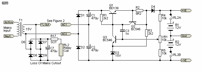
Figure 1 - Charger and Current Limiter
All unmarked diodes are 1N4004 or similar, and all resistors may be 1/4 Watt (see Table 1 for R8 & R14). Multiturn trimpots are recommended for VR1 and VR2. C3 should be polyester (or similar), and rated at 50V, C1 and C2 should be rated at 50V or higher. Other electros may be 16V types. D3 is a 15V 1W zener diode. All other components are as marked. Q1 must have a heatsink!
The circuit above has D4 before the output voltage divider. Omitting this would cause a continuous drain of about 800µA, which although not much, will discharge the batteries if left long enough without mains power. In addition, there's another small load from the sensing circuit (about 3.5mA), and this will also cause problems if no mains power is present. As a result, the 'Loss of Mains' detector has been added.
By adding a relay (K2), the battery is completely disconnected from the charger and sense circuits if mains is not present. While optional, it's recommended. The resistor (R17) marked 'SOT' needs to be selected to obtain close to 12V across the relay coil. For example, a 12V relay with a 500 ohm coil will need approximately 330 ohms ½W. This extra circuitry is an update of the original circuit, which lacked anything to ensure the batteries wouldn't be discharged completely if one were to go on holidays (aka 'vacation') and forget to disconnect the battery before leaving.
Note that K2 is energised continuously as long as mains is present. While this does use a small amount of energy, it's under 0.5W. Make sure that the relay contact rating is sufficient to pass the current drawn by the preamp (or whatever is powered from the ±12V battery supplies). A diode is not necessary across the coil of K2, because the capacitor (C7) discharges relatively slowly and there is little or no back-EMF.
The AC from the transformer to the charger is connected and disconnected via K1 - a 12V relay. The contacts are connected as normally open (i.e. the relay must be energised to connect the charger). Because current is generally very low, a small DIL relay will normally be quite sufficient, provided that the contact current rating is at least 500mA or so. Most DIL relays will manage that with ease, but you must check to make sure. Reed switches (as used in reed relays) can usually handle about 1A continuously. When the relay closes, there will be a much higher inrush current as the filter capacitors charge. Some basic tests I've run indicate that this should not be a problem.
K1 can be a cheap reed relay - these usually have a very high coil resistance, so the current is reduced dramatically. Typical coil current is about 12mA, compared to a 12V DIL relay, which is likely to have a coil current of over 30mA. Since the relay must be powered from the battery while it is on charge, it is important to keep the current as low as possible to make sure the charging current to the battery is not reduced too much. Of course, it's also easy to increase the charge current if needed, by reducing the value of R2.
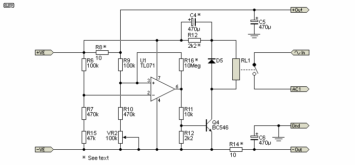
Figure 2 - Sensor and Relay Circuits
In Figure 2, I have shown the relay connections, together with an 'efficiency circuit' (R14 & C4), that will reduce the holding current to the bare minimum. C4 is used to provide an initial full voltage to the relay coil, to ensure that it will pull in reliably. After C4 is charged, the only current flows through R14, and the current is just sufficient to keep the relay energised, so current drain is minimised. You will need to adjust the value of R14 depending on the relays used - as shown, it is suitable for a 12V reed relay with a coil resistance of around 1k ohm, and limits holding current to approximately 8.75mA. R16 is optional but (with caveats) it might be alright. The idea is to ensure that switching is 'clean', with no relay chattering. In some cases, you may find that R16 causes the circuit to misbehave, and if this happens with your circuit it should be omitted.
The series combination of R7 and R15 can be replaced with a single 510k resistor if preferred.
The sensor works by detecting the voltage dropped across the sense resistor. When current is drawn, a small voltage is developed across the sense resistor (R8), and this is used to switch the opamp from a normally high output state to a voltage of about 2V. This switches off Q1, which in turn de-activates the relay and disconnects the charger. When the external circuit is switched off, the voltage across the sense resistor falls to near zero, the opamp changes output state, and the relay is energised, thus reconnecting the charger. Note that the opamp and relay driver are powered directly from the battery terminals, so their current is not monitored.
The charger must be able to supply enough current to keep the relay energised, as well as provide power to charge the batteries (and power U1 - typically about 2.5mA), so minimising relay current is important. The total current drawn by the opamp, current sense detector and opamp will be around 3.5mA, plus the relay current. Since the latter depends on the relay you use I can't provide a total figure, but once known, remember that this is subject to the current limiter in Figure 1, and reduces the battery charge current by the amount drawn by the circuitry.
If you switch the power to your external equipment on-off-on quickly, you may find that the relay does not re-activate after the last power-off. This can happen if C4 is charged, and has not had time to discharge fully, so the relay coil doesn't get the 'pulse' needed to close the contacts. The easy way to prevent this is not to switch off and on rapidly.
 |
Note: If the battery is allowed to discharge too far, there may not be sufficient charge for the relay to activate. An
'emergency' switch may be used in parallel with the relay contacts to force charge the batteries under these conditions, but you must remember to turn
it off again, or the automatic function will no longer work. It is recommended that any battery powered circuit has a low voltage disconnect function to prevent excessive battery discharge, which will shorten the life of the batteries (sometimes dramatically!). |
Finally, we need to establish a suitable resistor value for the sensor. Naturally, the optimum value depends on the current drain of the attached circuit(s). Table 1 shows the values that should be used for a range of loads, and in each case, we need an absolute minimum of about 10mV drop (and preferably closer to 100mV) across the resistor to ensure reliable detection.
| Minimum Current | R8 & R8/ R13 Value |
| 10 mA | 10 Ohms, 1/4W |
| 20 mA | 4.7 Ohms, 1/4W |
| 50 mA | 2.2 Ohms, 1/2W |
| 100 mA | 1 Ohm, 1/2W |
| 200 mA | 0.47 Ohm, 1W |
| 500 mA | 0.22 Ohm, 1W |
| 1 A | 0.1 Ohm, 1W |
As you can see, the relationship is quite simple, and may be extended as required. The values shown are likely to cover the vast majority of cases however. R13 should be made the same value as R8 - the voltage difference will only be very small however, and it may be omitted if desired. C5 and C6 are recommended, and may be increased if you wish. At higher load currents, the value should be increased, up to any value you are comfortable with. This will depend to some degree on the equipment being powered, and again, this is left to the reader to determine.
Construction is not critical, and all circuitry can be built on Veroboard or similar. The opamp needs to be FET input to minimise input offset current, which may change the trigger point with differing room temperatures. The TL071 shown will be perfectly acceptable, or you may use any other Single FET input opamp you have in your junk box.
R6, R7, R9, R10 and R15 should ideally be 1% tolerance metal film, or the stability and 'setability' of the sensor will be compromised. All other resistors can be 1/4W, 5% carbon, with the exception of the current sense resistor (see Table 1 for values and ratings).
Note that there is no earth (ground) on the charger circuit, and it 'floats' across the two 12V batteries. As a result, do not make voltage measurements referred to the equipment common (earth), or you will get erroneous answers! All measurements on the charger must be made with respect to the -ve end of C2.
Wire up all sections as per the circuit diagrams shown, taking particular care with polarised components (diodes, electrolytic caps, transistors and the opamp). Incorrect polarity will destroy many parts. When the charger is complete, it should be tested first (see below) - when that is working, make up the rest of the circuitry. Large components (e.g. electrolytic caps in high values) may need to be mounted so they have some mechanical support.
Test the charger circuit first. Connect to a suitable 15V transformer (a plug-pack (wall wart) type is quite suitable), and a 20VA unit will be sufficient). You need to short the relay contacts so the charger will operate, and if you install an 'emergency' switch in parallel with the relay contacts, simply turn that on. The use of a 100 ohm 5W resistor in series with the transformer is recommended for initial tests, so that a fault will not cause excess current and damage.
If all is well, the voltage at the +ve end of C1 should reach about 30V or so referred to the -ve end of C2. Adjust VR1 until the output of the regulator is at the correct voltage for your batteries, i.e. 27.6V for a pair of 12V SLA batteries, or 28.4V if you have assembled a Ni-Cd battery pack for a nominal +/-12V supply. Remove the 100 ohm resistor when you are sure that the charger works correctly.
Reconnect the AC supply to the charger - it is time to verify that the current limiter works. Use the 100 ohm resistor again - but this time, connect it between the +ve and -ve outputs of the charger. At about 90mA, it will get hot very quickly, but the output voltage (across the 100 ohm resistor) should be between 9 and 10V. Once this is tested and working, you can move on to the detector circuit.
Ideally, you will have your battery pack completed, and charged. If not, connect it to the charger overnight to make sure that it is fully charged and ready. Connect the remaining circuitry to the batteries and charger, and verify that the charger is operating. If not, you may need to adjust VR2 until the relays energise and start the charger. Now, switch on your equipment.
As soon as current is drawn by the preamp (or whatever), the charger should immediately be disconnected from the batteries. Verify this by checking that the voltage at the +ve end of C1 is falling towards zero, or simply measure the AC input voltage to the charger (after the relay). You may need to experiment a little with VR2 until the charger reliably cuts out as soon as current is drawn, and re-connects when the load is removed.
Once testing is complete and the circuit is working properly, it may be forgotten completely - your batteries will remain charged, and there will be a pure DC supply for your equipment whenever it is being used. Note that if you use a Ni-Cd battery pack, it should be fully discharged a couple of times a year to help minimise the 'memory effect' that these cells can exhibit.
While Li-Po (or Li-Ion) batteries would seen the obvious choice for this project, they must use accurate call balancing circuitry when being charged, or there is a serious risk of fire. As many would know, house fires have occurred all over the world from lithium cells and batteries, with a wide range of affected products. See Lithium Cell Charging & Battery Management for more details.
I expect that most constructors would prefer a system where it can be left on permanently, without the ever-present risk of the unit burning down the house. Lithium battery makers (and many of the products that use them) state categorically that the battery or product should not be unattended during charging. This even applies to many of the single-cell devices that are now common (smart phones being one of the most common).
Because of the risks of lithium, a more stable chemistry is preferable for non-portable hi-fi applications. Bulk and weight are not problems for gear that you don't have to carry with you, and the ability to leave the system running all the time with little fear of catastrophe is ... comforting. 
 Main Index
Projects Index
Main Index
Projects Index