
|
| Elliott Sound Products | Project 95 |
I have had a lot of queries about getting a low power negative supply in cars, to power Linkwitz transform circuits and the like. There is a switchmode converter, but I must admit that it is overkill for what most people need.
Another project describes how to generate an 'artificial earth (ground)', but this seems to have created more confusion than it's worth. In addition, some readers have had a great deal of trouble - especially with the transform circuit, because it has so much bass boost. In some cases, this can lead to instability - low frequency oscillation, commonly called 'motorboating' because of the sound it makes.
The instability is caused by the supply varying. As the circuit powers up, it will pass some signal to the subwoofer amp, which will draw current. The current causes the voltage to drop, and this is coupled back into the transform circuit, which amplifies the small change, and causes the power amp to draw more current. This continues until a oscillation condition is established, and the sub will just make "ga-bloomp, ga-bloomp, ga-bloomp" noises (or something similar  ) but nothing will work properly.
So, in answer to this, a simple little project will provide you with positive and negative supplies, allowing a true chassis ground connection, and will be suitable for preamps, equalisers, etc., provided the current is below about 20mA or so.
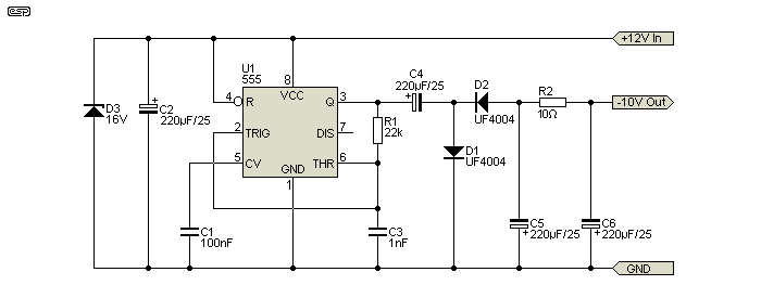
The circuit is very simple, and is easily made on Veroboard or similar. Construction is not critical, and the schematic is shown in Figure 1. Rectifier diodes should be ultra-fast (UF4004 or similar), or you can use 1N4148 signal diodes. Losses will be slightly higher if you use signal diodes, or lower if you use Schottky diodes. The small voltage gain is probably not worth the cost (IMO), especially because the circuit is only low current. The zener diode is to protect the circuit against transient overvoltage, and is optional (but recommended).

Using only a standard NE555 timer and a few other parts, this circuit should be up an running in about an hour. The 555 is configured as a minimum parts count astable (i.e. no stable states) multivibrator, and runs at around 21kHz with the values shown (simulated result - the actual frequency should be a little higher). The zener diode (D3) should be a 16V/ 1W type. Resistors are 1/2W carbon film, and small caps may be polyester or Mylar (63V types are quite Ok in this circuit).
Use a standard (bipolar) NE555 timer - not a CMOS type. CMOS timers do not have the output current of the bipolar types, and output voltage will be lower.
The circuit itself is a simple voltage doubler. You may well ask why the output is not -24V if the circuit is a doubler. Look at the circuit, and you will see that the output of the timer is AC coupled with C4, so it is actually only 6V RMS with a 12V supply. For an input of 13.8V (standard car voltage), the doubler action gives an output of -12.5V with no load. There is a small loss due to the diode forward voltage, and additional losses in the 555's transistor switched output.
You can also use an LM386 configured as a squarewave oscillator. It uses a few more parts, but can provide a bit more output current than a 555. C7 (10µF) is optional, but it provides higher gain and a little more output voltage. I've shown Schottky diodes, but you can use high-speed diodes (UF4004 or similar) if preferred.

The coupling and output capacitors can be reduced to 100µF, as can C6 (supply bypass). The zener diode is only needed for automotive applications, and it can be omitted if the circuit is powered from a regulated 12V supply. You can use a 15V supply, but only if the IC is the LM386N-4 variant. For 12V operation you can also use the NJM386 which may be cheaper. The LM386 and NJM386 datasheets include a circuit for a squarewave oscillator, but the version shown above works better at high frequencies. As simulated, the frequency is around 65kHz, and it can be changed by altering the value of C2. A higher value produces a lower frequency.
This version is adapted from 'Comparing the NE555 Timer and LM386 Amplifier as Inductorless DC-DC Converters', published at electronicdesign.com. Please note that it has been simulated, but I've not built the circuit. The frequency of a 'real life' LM386 may be different from the simulation. You may need to experiment a little with the values of R1, R3 and C2. Alternative values are 2.2k, 22k respectively, and around 3.3nF for C2. C1 can be increased to 1µF if desired (positive to pin 5 if it's an electrolytic). The LM386 is not a precision part, so results will vary.
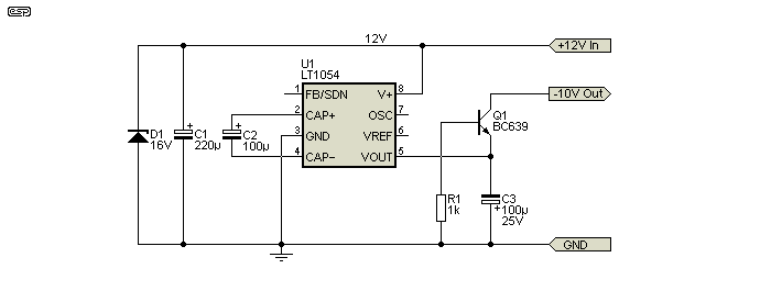
It's hard to get anything simpler than the LT1054. It's specifically designed for the purpose and only needs a couple of capacitors (plus a bypass cap) to generate a negative voltage. It also includes a regulator if required, and the details are in the datasheet. The IC is made by Linear Technology and Texas Instruments, but don't expect to find it in retail electronics shops. It should be readily available from major distributors, and it normally costs around AU$4.50 or so.

I've shown only the most basic application, with no regulation. The typical oscillation frequency is around 25-30kHz. It's not necessarily quite as straightforward as it first appears, because the load (typically opamps connected between +Ve and -Ve) can easily force the negative output slightly positive. This will stop the LT1054 from starting, and the datasheet recommends using an external transistor to prevent that possibility. This will be required in almost all common applications.

The MAX1044 is another suitable candidate, but it's limited to a 10V supply. It's more expensive than the LT1054, but you don't need the extra transistor. Like the LT1054 there are many options, but for a simple negative voltage converter you won't need any of the more advanced features.
Since there are no plans for a PCB, make the circuit on Veroboard or similar prototype board. All currents are low (no load current is only 10mA, rising to 30mA with a 20mA output current), so special techniques are not needed. The final filter shown (R2 and C6/ C5, Fig 1 & 2) is needed to remove switching noise from the output. You may also need additional filtering for the Fig. 3 circuit.
Make sure that you don't locate the circuit or its supply leads near pre or power amplifier input leads. The switching frequency is high enough to be inaudible, but could potentially damage tweeters if it were to be amplified.
Before connecting to a car battery supply, test the circuit first, using a 9V battery. If there is a problem, the IC may still be damaged, but at least it will not blow up in your face, or cause the smoke to escape from the supply leads (light duty leads are quite sufficient, as current drain is low). From 9V, you should see at least -7V output with no load.
Note: When either of these circuits is used, the positive and negative supplies will not be equal. This is quite ok with the vast majority of opamp based designs, but there may be some designs that will not work if the supplies are not balanced (these will be very rare, but it has to be mentioned).
If you wanted to do so, low power 9V regulators may be used on the +ve and -ve supplies, but this will not provide any real advantages to most opamp circuits.
Depending on your supplier, you can get an isolated DC-DC converter as a tiny 'component'. They are made by many manufacturers, including Recom, CUI, Traco Power, Murata and MeanWell. They range in price from around $5 to $12 or so. They are far smaller than anything you can build, and a 12V 1W version can supply 84mA. Being isolated, you can wire the output to get a 24V supply from 12V, or ±12V. I've used them in a number of projects, both for myself and customers.
These converters are available with a wide range of input and output voltages, and are very convenient. Some additional filtering is usually needed for audio, but it's no harder than that shown for the two supplies above. If you need more than ~50mA, the 10Ω resistor can be reduced, or you can use a small inductor. Around 220µH should be more than enough. Make sure that the DC current rating for the inductor is greater than the current drawn by your circuit.
These converters are typically about 10mm high, 12mm long and 6mm wide, with four inline pins. Isolated versions have a completely floating output, and they are normally rated for at least 1kV (1 minute). However, most are not designed to withstand mains voltage, so cannot be used in any application that involves the mains. That's not a consideration when used to provide a negative voltage to power opamp circuitry, but it is important to understand the limits of any device you use.
 Main Index
 Projects Index