
|
|
| Elliott Sound Products | Project 80 |
I came up with this idea when I was in a situation where ...
So I designed a miniature passive network to convert a normal audio signal into the signal that phono inputs require.
As the amplification of a phono input is quite high, this pre-equaliser network can be made completely passive. The frequency response of the current through the network formed by R1, R2, C1 - C4 corresponds to the inverse of the standard RIAA curve, so these components determine the frequency response of the circuit. The current produces a proportional voltage across the operating resistor R3. This resistor determines the output voltage or the overall voltage gain. I selected it so that with my amplifier the standard (DIN) inputs show the same sensitivity as the phono input with this adapter.
Figure 1 - Reverse RIAA Filter
R3 influences the frequency response at the upper end. If R3 becomes too high, high frequencies are reduced. With R3 = 1.5k the reduction is less than 0.1dB @ 20kHz, with 10k it's about 3dB.
Any capacitance on the RIAA input up to 50pF or more is negligible. Source resistances up to 1k will also have little effect, and this fits well to low resistance RCA or headphone outputs.
| Ideal | Actual | Alternative | |
| R1 | 883k | 909k | 910k |
| R2 | 75k | 75k | 75k |
| C1 | 3.6n | 3.3n | 3.3n |
| C2 | - | 270p | 330p |
| C3 | 1n | 1n | 1n |
| C4 | - | - | - |
| R3 | 0 | 1k | 1 - 1.5k |
The ideal frequency response cannot directly be achieved by standard components. It must be approximated and in this case the approximation is improved by paralleling two capacitors each as required. In the table you find ideal and practical values for all components. The resulting frequency response and the difference to the ideal frequency response is shown in the plot.
Use of the actual/ alternative values shown will result in an almost negligible error, and these are standard E24 series components ( )
)
Components were selected from the E96 series for resistors and the E6 series for capacitors. Of course all values may be different, but their relations to each other must be as close as possible to the ones in the ideal circuit.
Figure 2 - Frequency Response
In the upper plot the frequency response of the ideal and the real circuit is shown, in the lower one the difference between both.
The All-In-One-Plug-Solution
My personal aim was to build the whole circuit stereo into one DIN connector. This is why I chose a circuit with all elements (except R3) tied together at one centre point. So I could build the element building block shown in the photo from 0805-SMD-components. Two of these fit easily into one DIN connector together with twice R3 (see photo), but a single circuit surely would fit into a cinch (RCA) plug as well.
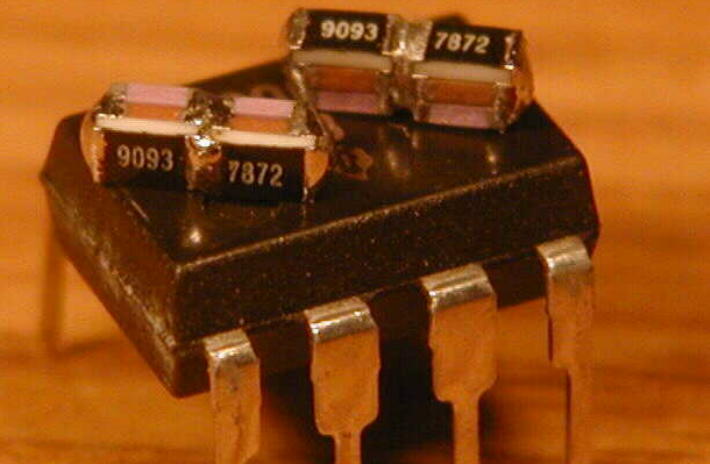
Figure 3 - Photo of SMD Version (IC for Size Comparison Only)
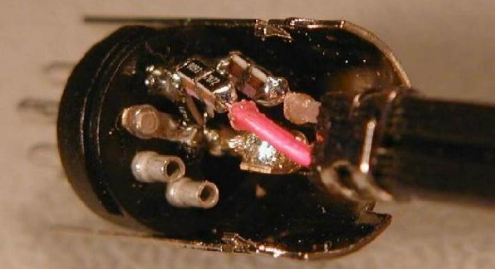
Figure 4 - Complete Stereo Version in DIN Connector
Although Uwe designed this circuit to utilise an otherwise unused phono input, it can also be used to test phono stages for frequency response. By feeding a high level (1V RMS) signal into the circuit, a quick check of the response of any phono preamp is easily done. The combined response should be flat within 1dB - if not, the phono equaliser is not accurate.
Most readers will build this circuit using conventional resistors and capacitors, and this is perfectly alright. The values need to be as close as possible to the values calculated by Uwe (or the alternative values I included), or overall performance will be adversely affected.

Figure 5 - Reverse RIAA and P06 Phono Preamp
Figure 5 shows the combined response with the reverse RIAA equaliser and my (favourite) phono preamp - Project 06. The slight boost in very low bass and negligible boost in treble is seen easily - these account (in part) for the very favourable comments about this phono preamp, and also show how accurate it is. The inaccuracy is shown to be better than 1dB at most frequencies, but with a slight improvement in the lower bass region.
The inaccuracies indicated here are very minor, and are especially so when compared to the wide variations in the mix quality of typical vinyl recordings (actually, any recording, regardless of medium). While it is common believed that RIAA equalisation should be accurate, no-one knows how much EQ was applied to the original recording, so I maintain that there's no real point trying to get better than around +/-1dB. What is important is the matching between channels.
A CD player could easily be used with this combination, and the only penalty (in realistic terms) would be a slightly higher noise level - you may be able to hear hiss at perhaps a metre away, instead of having to stick your ear in the tweeter.
Another version is shown above (designed by Peter Walker of Quad). The impedances are lower, and that should result in lower noise. However, it also presents a much lower impedance to the source, and some circuits may have problems driving it. At 20kHz, the input impedance is only 500Ω, which is likely to cause problems with circuits that cannot drive low impedance loads. Input impedance at 1kHz is about 4.7k which any decent circuit can drive easily.
Figure 6 - Alternate Reverse RIAA (Quad Design)
This has identical frequency response to the version shown in Figure 1, but the source impedance has to be very low. With a (more-or-less) typical source impedance of 100Ω, the response is down by about 0.4dB at 20kHz, and is down by 0.12dB at lower frequencies. This is to be expected because the load impedance is only 47Ω. I suggest that the source impedance should be no more than 10Ω. The values needed can be made up with those you can get. For example, C2 (16nF) is 15nF + 1nF, and C1 (46nF) can use 39nF + 6.8nF. A simulation shows that the 200pF discrepancy is of no consequence (0.004dB error at 20Hz).
The reverse RIAA circuit shown in Figure 1 was originally designed by Reg Williamson, and was subsequently modified for greater accuracy by Lipschitz and Jung (Audio Amateur, 1980). A copy of the article is archived on the ESP site. (Click here to see it.) The PDF used to be available at Walt Jung's site, but it no longer exists there.
 Main Index
Projects Index
Main Index
Projects Index