
|
|
| Elliott Sound Products | Project 46 |
The thermal protection of amplifiers is always a concern, since overheating is a sure way to reduce the life of semiconductors and other components. Where you don't want to use a fan (such as in Project 42 - Thermo-Fan for Amplifier Cooling), then a complete shutdown can be performed.
This project is really a mixture of ideas, some simple, and others even simpler. The system I have installed in my biamp unit is fan cooling. Once a preset temperature is reached, the fans start, and remain on until the amp is turned off again. This is crude, but very effective. It only operates if I am listening LOUD on a very hot day, which means that the fans have probably only operated about 5 times in their life. I do know about it when they operate because they are fairly noisy (although I have reduced the operating voltage which quietens them down a bit), but at least I know that the amp is protected.
Even simpler is to just switch off the power when the amp overheats. I would use this as a backup to the thermo-fan or fan controller if I left the amp powered on all the time. While I don't do this, a lot of people do, and although it does waste a certain amount of electricity, the greatest concern is fire.
At least a simple precaution or two should be taken to ensure that one does not come home to a pile of ashes that used to be a home - this actually happened to a friend of mine, and from what I saw, there is not a lot to recommend it.
 |
WARNING. This project relies on your ability to wire mains voltage circuits. Do not attempt construction unless you are confident that your efforts will not result in death or injury. |
Because I use Australian conventions for mains (Active, Neutral and Earth), you might need to translate these to the conventions where you live. They are sometimes referred to as Line, Neutral and Earth (UK), or Line-Hot, Line-Cold and Ground (one - of many - US conventions I have seen).
Basically, the active is the lead that will kill you, the Neutral is the lead that MIGHT kill you (if the plug or socket is wired incorrectly), and Earth is the safety grounding lead (Green-Yellow nearly everywhere for new equipment).
The simplest of all is the thermal switch. These are used in washing machines, dish washers, microwave ovens, and many other appliances, and can be obtained from an appliance repairer for less than $10 (they are generally about AU$4.50 or so). The switches need to be screwed down to heatsinks using thermal compound, but should be glued to transformers using a suitable adhesive (see below). Make certain that the tags are properly insulated to prevent electrocution - this is VITALLY important.
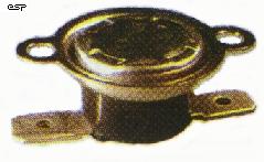
Thermal Switch
Figure 1 shows the connections for the type of unit I refer to. These switches are available in a variety of temperatures, normally open, normally closed, etc. For amplifier protection, you need up to three normally closed thermal switches (TS1 to TS3), rated at no more than 80°C. These are for the power transformer, and one for each heatsink. The incoming mains (after the power switch and fuse) is routed as shown through each of the thermal switches, and finally to the transformer primary.
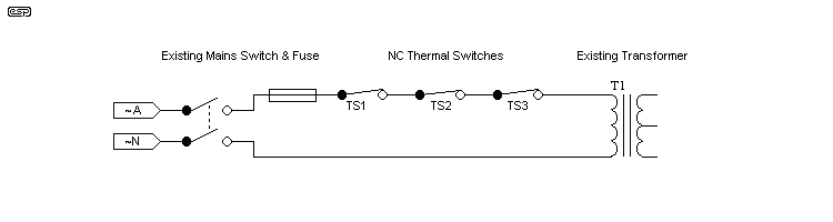
Figure 1 - Thermal Switch, And Wiring Diagram For Three Switches
Should any of the protected items exceed the switch temperature, the amplifier will be turned off. It will turn back on again when it cools enough for the switch to reset. In the case of a fault, the amp will turn off and back on again until the problem is rectified, but at least there is protection.
Where it is not possible to screw the switch to the item (such as a transformer), a high temperature epoxy can be used. Do not use Super-Glue or similar, as it is unsuited to the task. Likewise, don't use the 5-Minute "epoxies". They are not true epoxies, and cannot tolerate the sustained heat. True epoxy adhesives take about 24 hours to cure properly, and once cured are extremely robust. At the risk of an unpaid advertisment, I would suggest the 24 hour cure Araldite - NOT the 5-Minute one. Clamp the switch to the surface until the adhesive has cured - this can be done easily with painters' masking tape for awkward shapes.
Use the adhesive sparingly - some of these switches are open at the contact face, and if epoxy enters the internals of the switch it may ruin it.
For a thermal fan, a simple detector using a thermistor (or a number of thermistors) senses that the temperature is above a preset limit. Once this is reached, the fan(s) start, and will then run until the temperature is below the threshold again. This is an updated version of the system I am using at present. The main problem is the general unavailability of thermistors! As a result, two circuits are shown. Select the one you want based on whether you can get the thermistors or not.
The simplest AC switch is a TRIAC, which will turn on if the gate voltage exceeds the internal trigger current. As long as the current remains, the TRIAC will continue to conduct. TRIACs can be irksome to drive with DC, so the MOC3021 opto isolator provides excellent electrical isolation, and ideal TRIAC triggering. This way, we can use mains voltage fans using AC, rather than the Thermo-Fan project, which needs DC fans and runs off the main amplifier power supply.
Although DC fans are cheap and easily obtained, they are not as powerful as most AC fans, and are generally fairly low quality - although there are many computers out there that have been running for years, and the fans are still fine.
AC fans can be made quieter by reducing their voltage, and the easiest is to use a resistor. This will need to be a high power wirewound type, and make sure that the terminations are properly insulated. I will have to leave it to you to experiment to find a suitable value resistor.
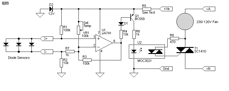
Figure 2 - AC Fan Controller
This circuit is based on the thermo-fan design, but now switches a TRIAC, using an opto isolator specially designed for the purpose. I experimented with simpler circuits, but was highly unimpressed with the results, so in the interests of making a reliable and predictable protection unit, decided on the slightly more complex solution. See Figure 4 for the pinouts for the opto-coupler and TRIAC. To calculate the value of R5, use the formula for the thermistor version (substitute R5 for R3, otherwise the formula is the same).
The simplest way of all is to use a thermistor, which can be almost anything you can get hold of, but in Australia, none of the popular retail suppliers has any thermistors that I have found, and they are not at all common any more. Pity, because they are very easy to use. If you can get them, Figure 3 is by far the simplest way to control the fans, but it will require some degree of experimentation, since I cannot predict what sort of thermistors may be available where you live.
The NTC (Negative Temperature Coefficient) thermistors are RT1 to RT3, but you can add more or use fewer than this as needed. The trimpots make it easy to make fine adjustments for each thermistor. If you can, try to get thermistors with a nominal value of about 10k (at 20 degrees C). A trimpot and diode is needed for each thermistor to prevent interaction between the sensing circuits.
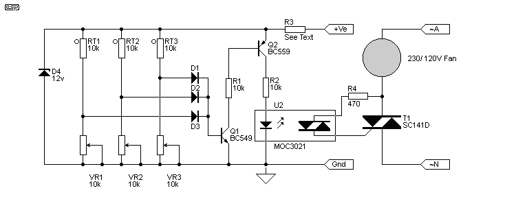
Figure 3 - Thermistor Version
I still used the TRIAC isolator / trigger IC, as this is the easiest way to trigger the TRIAC reliably and maintain safety. The thermistors supply the bias to Q1 as the resistance of any one of the thermistors falls with increasing temperature. Q1 turns on Q2, which supplies LED current to the MOC3021.
The zener current needs to be about 20mA. Knowing this, R3 can be calculated -
R3 = (+Ve - 12) / 0.02 where +Ve is the amplifier supply
As an example, assume that your amp has +/-50V supply rails. We will also calculate the power rating for R3 -
R3 = (50 - 12) / 0.02 = 38 / 0.02 = 1900 Ohms (use 1k8)
R3 = V² / R = 38² / 1800 = 1444 / 1800 = 0.8W (use at least 2W)
Electrical safety is (as always) critical. There should be no track material between the pins of the MOC3021, and a completely bare section of board (whether PCB, perforated or Veroboard) must be left between all low voltage circuits and high voltage circuits. This safety zone must 5mm MINIMUM. Likewise, there should be 5mm minimum between any live (mains) board wiring and chassis. All mains wiring should be shrouded with heatshrink tubing or plastic insulating sheet to ensure that human contact is not possible.
The TRIAC and MOC3021 (US readers can use the lower voltage MOC3020) are shown in Figure 4.
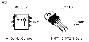
Figure 4 - MOC3021 and TRIAC Connections
The terminal marked * must not be connected on the MOC3021. Unlike transistors or FETs, TRIACs do not have a sensible designation for the main terminals, and they are referred to simply as MT1 and MT2.
The direction of airflow is important to ensure maximum cooling. Computers do it the wrong way around, by sucking air across the power supply. This was done for aesthetic reasons, and has nothing to do with efficiency. Someone decided (perhaps not unwisely) that air coming through disk drive slots and other orifices in the computer cases would be annoying to users, so the fans were reversed.
If you want to cool a heatsink - blow air onto the surface. This creates turbulence that disrupts the laminar airflow, and allows cooler air to come into direct contact with the surface of the heatsink. If air is sucked past the heatsink, this is nowhere near as effective. If your spoonful of soup is too hot, do you blow or suck air across the spoon? I rest my case.
 Main Index
Projects Index
Main Index
Projects Index