
|
| Elliott Sound Products | Project 32 |
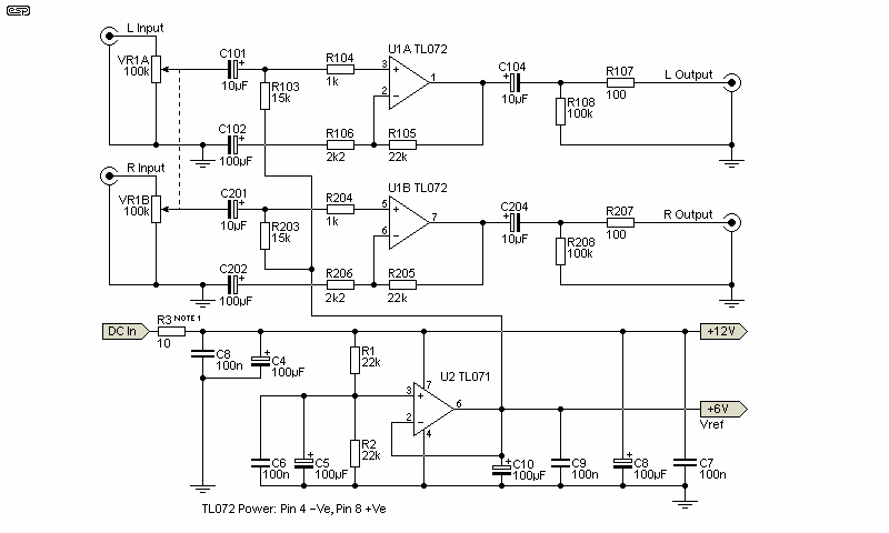
Prompted by a reader's question, this is a useful addition to a car audio system, especially if one wants to use a crossover circuit and other low level amplifiers. The circuit contains two audio preamps, with a maximum gain of 21dB (this can be reduced, as it may be too high for many applications).
Also provided is an 'artificial earth' ('ground' for US readers), which can be used to supply a centre voltage for crossovers and other additions - such as a parametric equaliser, or even a simple graphic equaliser. Finally, there's also a general purpose artificial earth or pseudo-split power supply that can be used with many opamp circuits.
The input impedance is a minimum of 15k (it will be much more than this for most control settings), and output impedance is 100 Ohms - low enough to drive any line level input.

| Please Note: An artificial ground does not (and is not intended to) relace the 'real' ground. It's a reference that's typically at ½ the supply voltage, and is used for biasing. It should not be used as the return for opamp (or other circuitry) feedback networks, which will ideally be connected to the actual ground via a capacitor. This point seems not to be well understood, as I keep getting emails asking why feedback isn't returned to the artificial ground. |
The preamp circuit is completely conventional, and by necessity is AC coupled throughout. The artificial earth is derived by two resistors (R1 and R2), which will set the 'earth' at exactly 1/2 the supply voltage. This is nominally 13.8V in all cars, since this is the proper charging voltage for a 12V battery. The voltage may be up to 14.4V, but this does not affect operation.
To reduce the maximum gain, simply reduce the values of R105 and R205. For example, reducing these to 4k7 will provide a maximum gain of 3 (10dB), which in reality is probably enough.

Figure 1 - The Circuit For The Preamp
Note - There is quite a lot of filtering, because the vehicle supply is notoriously noisy. In some instances it might be necessary to replace R3 with a suitable noise filter module, an inductor, or both.
The artificial earth is obtained from the '6V' (Vref) terminal, and is used in place of the real earth connection for the additional circuitry. It may (will) be necessary in some cases to either ...
In addition, electrolytic capacitors in feedback circuits that are connected to earth should be connected to the actual (chassis) earth, not the artificial earth, or performance may suffer. Because the artificial earth/ ground is not the 'real' ground, it has a finite impedance. This can cause unwanted interactions and in extreme cases can lead to low-frequency instability.
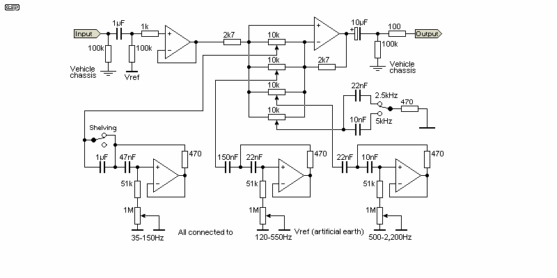
As an example, I have included the circuit for my parametric equaliser and sub-woofer equaliser (Project 28), with the required modifications shown. The same principle applies to crossover networks or any other signal processing circuit.

Figure 2 - Modified Version Of Project 28
As can be seen, all the original earth connections except the one new one (the 'Vehicle Chassis' connection) go to Vref (the artificial earth). If this is not done, the circuit simply will not work, as it will be trying to function with the input at the same potential as the negative supply terminal on the opamp.
One word of warning - if the device you are connecting to the artificial earth is expected to have significant AC or DC earth currents (> 10mA), this system will not work. It is designed for low current (preamp) type applications only. A higher powered version could be developed from the basics presented here, but as long as high level current is kept away, this design should be quite acceptable. It's a scheme that I've used countless times, and if the guidelines described are followed it will work every time.
By the way, the above circuit would be an ideal addition to almost any car sub-woofer installation, leaving out the upper midrange and treble controls (they are not useful for a sub). Alternatively, you could have two of the 35-150Hz controls, which will give much better control of the lower bass region. The 120-550Hz control is likely to be useful to eliminate unwanted peaks (or dips) over the crossover region. You may want to lower the frequency, by increasing the value of one or both capacitors for this control. Doubling the value of either cap will halve the frequency (i.e. from 60 to 225Hz).
Most opamp circuits need a split supply, typically providing ±5V or more. In these circuits, there is little or no current in the earth circuit, so a very simple 'supply splitter' can be used. The circuit shown below is suitable for input voltages from 12V to 25V or so, and the 1,000uF caps need to be rated for at least half the total voltage. For example, if the input voltage is 15V, the outputs will be ±7.5V, and the electrolytic caps need to be rated for around 10V each. The 100nF caps are optional, and if used should be multilayer ceramic types.

Figure 3 - Artificial Earth/ Split Supply
Note that the supply must be fully floating, with no connection to chassis (so you can't use this in a car for example). Likewise, the DC input connector must also be fully insulated from the chassis (assuming the use of a metal enclosure). D1 and R1 (10 ohm fusible resistor) protect against reverse polarity. If preferred, you can use a normal 1W resistor for R1, and add a 250mA fuse in series.
The most common use for a circuit such as this will be to obtain a split supply voltage from a single output plug-pack (aka 'wall wart') supply. Be aware that it will not work properly (if at all) if the circuit you are powering doesn't draw an identical current from each supply rail. Most opamp circuits meet this criterion, but many discrete transistor circuits do not. During testing, verify that you have close to identical positive and negative voltages (±200mV or so) at each output with respect to earth/ ground.
If you wish to include a power-on indicator (an LED with a series resistor for example), it must be connected between the supplies (between positive and negative) and not between one supply and ground. If connected between one supply and ground, the supply will be unbalanced as a result. As shown, this supply will be fine for use with circuits that draw up to 100mA (you'll 'lose' 1V across R1). For higher currents, reduce the value of R1. A minimum of 1 ohm is recommended.
This power supply is not suitable for use with small power amplifiers - it is intended for use with opamp circuits only. Because the supply voltages are lower than normal (typically ±15V), the maximum signal is also reduced. With an external 15V supply, the maximum output level will be around 3V RMS, and less output will be available if the input voltage is lower. The external supply should be a minimum of 12V, because some opamps will not function properly (if at all) with supply voltages below ±5V. Unfortunately, it's close to impossible to obtain external supplies with 30V outputs, but if you can get a 24V version this is preferable to lower voltages.
 Main Index
 Projects Index