
|
|
| Elliott Sound Products | Project 31 |
 Main Index
Projects Index Main Index
Projects Index
|
When building amplifiers or any other power stages, it is often necessary to test transistors, either to verify that they (still) work, or for some esoteric designs it may even be necessary to match certain characteristics. Don't assume that because your multimeter (or small 'automatic' component testers) can test transistors so are capable of testing power devices, because they are not. The collector current is usually limited to a few milliamps at most, and that's completely useless for a power transistor which may not show any useful gain until it's conducting somewhere between 10 and 100mA.
I suggest that you also look at Project 106 (hFE Tester for NPN Power Transistors) and Project 177 (Constant Collector Current hFE Tester for Transistors). They are less complex than this version, and cannot test breakdown voltage (no high voltage supply), but you may find one of those to be a bit easier to build than the version described here.
The design featured here is just what you need, and provides the ability to test:
As with some of my other projects, this is not particularly cheap to build, but if my own unit is anything to go by will give many years of faithful service. (I have actually had mine for so long that the variable high voltage source used a valve - it has only recently been replaced with a transistor.) This design is actually better than my existing unit - it has a bigger power supply, and is more flexible in operation.
There are a couple of photos of my unit at the end of this article, so you can get some idea of what it might look like when finished. Bear in mind that this tester is different from mine (it has more features), so don't try to make a direct comparison of the switching. Mine (unfortunately) does not have the separate base current and collector current range switches, and is somewhat less useful as a result. Maybe I'll have to make one of these next.
Warning
One caveat I must make at the outset. Like any similar commercial offering, this tester is just as capable of blowing up a transistor as it is of testing it. It is entirely the responsibility of the user to ensure that the settings are correct before pressing the Gain switch. The author takes absolutely no responsibility for any damage, whether direct or consequential that may be done to the device under test or the operator due to the use or inability to use the project described. For example, if you leave the base current set for 10mA and the collector current range at (say) 1A or more, when you try to test a small signal transistor it will probably fail immediately. Always check the ranges before pressing the test button!
It's very doubtful that you'll be able to buy a transistor tester that matches the specifications and features of the design shown here. They were once at least available, but a recent search has shown nothing that comes even close. Microcontroller 'all purpose' testers are incapable of testing a transistor to a reasonable current, and while convenient, they cannot replace a dedicated tester. The 'testers' in some multimeters are even worse - they can only test at very low current.
The basic method for testing the gain of a transistor is shown in Figure 1, and although not the ideal, is far simpler to implement than using a fixed collector current. The results are more than acceptable, and because of the design of this unit, it is possible to observe gain droop and other undesirable phenomena up to the maximum current.

The final unit's range switching and other functional blocks are shown in Figure 2, and it can readily be seen that it is comprised almost entirely of switches and resistors. No printed circuit board is needed, since most of the resistors should be connected directly to the switches, or may be mounted on tag strips as I did in my original unit.

The meter range extends from the maximum meter sensitivity of 100µA in decade steps up to 1A. The highest range was limited to 5A deliberately - even at this current, the transistor will be dissipating up to 20 Watts worst case, so the device under test should be mounted on a heatsink, or the test should be kept to very short duration, otherwise the transistor will overheat and may (will) be destroyed or severely impaired.
In 'normal' mode (testing gain), the meter is in parallel with the shunt resistor selected by the 'Range' switch. The metering circuit is designed to provide full-scale with an input of 10V, which matches the current ranges. When measuring breakdown voltage, the meter is in series, from the variable high voltage supply to the collector of the transistor being tested. When the 'Voltage Test' button is pressed, the meter then reads the voltage between the collector and emitter. It's then in parallel with the variable high-voltage supply, with the voltage clamped by the transistor's breakdown voltage.
Power Ratings Of Resistors
The power ratings for the various meter shunt resistors are important. The 2 Ohm resistor (5A range) is best made using five 10 Ohm 10W resistors in parallel. The dissipation will be a maximum of about 70 Watts, but will only be used for a short time, otherwise the transistor will overheat and fail. Mount the resistors on a section of heatsink with an aluminium bracket, making sure that the bracket and heatsink make good thermal contact. Use some thermal compound to make sure that as much heat as possible is removed. Do not use the same heatsink as the power regulator. The added heat from the resistors will raise the temperature too far, and will endanger the life of the semiconductors.
You may wonder why I didn't use a 200mΩ (0.2Ω) resistor for the 5A range with the others also reduced in value by a factor of ten. The reason is that the values selected eliminate the need for overload protection for the power supply. If a 200mΩ resistor were used this would be mandatory, as the current could (attempt to) reach 63A if a shorted transistor were connected. The 10 Ohm resistor (1A range) should also be 10 Watts, but does not need a heatsink (although mounting it with the others will not hurt). You must keep it away from other components, because it will get very hot.
The 100 Ohm (100mA range) can be a 5 Watt unit, and will run quite cool (only 1.6W dissipation at worst), and all other resistors should be 1/2W types. Since absolute accuracy is not overly important, 5% tolerance is fine, but 1% can be used if you prefer.
Switch Functions
The various switches and functions are as follows:
Range Select the collector current measurement range. The resistors act as meter shunts, and are scaled to ensure that the maximum current (even from a shorted transistor) is only slightly greater than the indicated range. The collector voltage is nominally 12V, but as the device current increases this will fall. 
At the maximum meter reading, the transistor will have a collector voltage of about 2V. It is not necessary to maintain a constant voltage, as the gain variation with voltage is normally not great. The design would become far more complex if a constant voltage supply were used. R-be Sets the emitter to base resistance for breakdown voltage tests. Many transistors have a wide variation of the breakdown voltage between collector and emitter, depending on the resistance between emitter and base. This allows you to select a value and perform comparative tests. Base Current Set the base current to be used for gain testing. This ranges from 1µA up to 100mA in decade steps, and allows you to test all transistors from small signal devices up to high current (including Darlington) power transistors. Gain This is a momentary push button switch, which disconnects the emitter-base resistance and applies the selected base current. The transistor's gain is then worked out from the meter reading. See Using the Tester, below. NPN / PNP This switches all voltages so that both PNP and NPN transistor can be tested. High Voltage Turn the high voltage supply off when not in use (and make sure you do!) Voltage Test (Momentary Pushbutton) Measure the applied breakdown voltage Voltage Range Switch from 100V full scale to 500V full scale (requires a bit of mental arithmetic or a custom meter scale)
Figure 3 shows the switching for NPN and PNP (everything has to be reversed in polarity). Also shown is the meter and its calibration resistors and protection diodes. These will conduct when the voltage across the meter exceeds 0.65V, so if the same meter movement (or one passably similar) is used, a maximum overload current of 170µA is possible. Although this will cause the needle to swing hard against the stops, it will not damage the movement. The polarity switching needs a 6-way, double-pole switch, which will be a nuisance. The easiest is to use three relays with their coils in parallel (remember to add the flyback diode in parallel with the coils). The wiring is shown in the inset.
I have used an analogue meter movement because they are much simpler to implement, although they are usually somewhat more expensive than a digital panel meter. The latter needs a floating supply, and they are easily damaged by stray high voltages. The high voltage is used to test the breakdown voltage of the transistor, and will give a nasty bite, so I suggest that you treat it with great respect.
The meter movement is a standard 100µA unit, and I based the resistor values on the specified meter resistance of 3,900 Ohms. If the meter you use is different, then you must make some adjustment to the 82k and 15k resistors. The aim of these is to make the entire circuit has a resistance of 100k. Since 10V is developed across the shunt resistors for full scale, this means that 10V and 100k = 100µA. Of course you can use a multi-turn trimpot so the meter can be calibrated if you choose.
If you add up the values, we have 3.9k, 15k and 82k, making a total of 100.9k (better than 1%), which is more than good enough for this application.
The 4M Ohm meter resistor (marked *) can be made using a 3.9M in series with 100k. This needs to be fairly accurate, or the meter's voltage reading will not be useful. Note that the meter protection diodes are disconnected in voltage test mode, but remain connected to the rest of the meter switching circuit. This is to ensure that the load current on the HV supply is not changed when the Voltage Test button is pressed. If this was not done, the meter load would vanish, and the voltage reading would be meaningless.
Please note that the range switch is expected to carry up to 5A. This is probably at the very limit of the switch's capacity (depending on the unit used), but since the current is intermittent it will have a long and fruitful life regardless. I normally will never operate anything at (or above) its limits, but the cost of an alternative is too horrible to contemplate.
The power supply is not complex, but will need some ingenuity to ensure that the voltages are as specified. Using the second transformer as shown is not the most efficient way to create a high voltage / low current supply, but is by far the simplest and most reliable, and that is why I chose to do it this way. Using a switchmode boost converter is another way, but it must be fully isolated from the main (12.6V) supply to allow NPN/ PNP switching. Isolated high voltage converters are hard to find.
The main supply is quite conventional (well, almost), and uses a 7812 regulator to set the voltage. This is boosted by the diode to 12.6V (approx) to ensure that the base currents are accurate, and uses a bypass transistor to supply the 5A maximum current that I designed for. No current limiting is used, since it is not needed - even with the meter on the 5A range, a direct short can draw a maximum of about 6.3A which is well within the capability of the supply.
The regulator and power transistor must be mounted on a heatsink. Although it does not need to be massive (tests are normally of short duration), I suggest that a 1°C/ Watt unit would be ideal. The regulator should be isolated from the heatsink with a mica washer, but I recommend that the power transistor be mounted directly for the most efficient heat transfer. The heatsink will be operating at about 25V above earth with this arrangement, so internal mounting is suggested. Make sure that there is sufficient airflow for proper cooling. As noted above, the load resistors used mean that short circuit protection isn't needed, thus simplifying the PSU.
Suitable high voltage transistors for the HV supply include 2N6517C, KSP44TF, ZTX458 and STX83003. These are available as of 2015, but you may still have to search for them. The transistors originally suggested are no longer available, but the MPSA44 is fairly common. Other suitable devices include the BUL310FP or 2SC3749M. The transistor needs a voltage rating of at least 400V, and worst case dissipation will be around 250mW. It may also be possible to use a high voltage MOSFET (e.g. IRF840), but you must add a 12V zener diode between the gate and source pins or it will be destroyed - probably the first time you use it!
Remember that this transistor is operating with a maximum voltage of over 300V, so don't try to use any device with a rated voltage of less than 350V (minimum). Make sure that it is designed for low current operation - many high current transistors have very low gain at low currents. The transistor I used originally (no longer available) is actually rated at only 225V, but one of the really nice things about having a tester like this is you can select transistors that are often considerably better than their specifications.
The series resistor to the HV+ supply line is a compromise. It needs to be high enough to prevent the transistor (or the user) from being damaged, but also needs to be low enough to ensure that a workable breakdown current can be achieved. You typically need around 20-100µA or so to test the breakdown voltage of a transistor. If the current is too high the transistor under test may be damaged.
The high voltage supply uses a second transformer, and I suggest that a voltage of about 300V DC is sufficient. There is no reason that this cannot be increased (other than locating a suitable transistor), but for audio work it is not generally necessary. Be warned that the high voltage has the capability to kill you, so don't get careless with it while the tester is being built.
All diodes in the circuit should be as indicated, and use a 10A or 25A bridge rectifier. Make sure that all mains connections are properly insulated to prevent accidental contact. This includes the HV section, which is still dangerous at all points in the circuit. The resistor/ diode and LED circuit (bottom left) can be connected across the secondary winding (input side) of the HV transformer to indicate that the HV supply is on.
Note:
The high voltage supply is needed only for breakdown voltage tests, and you may choose not to include it. If this is the case, everything is simplified, but of course you can't test breakdown voltage. In most cases, this is probably the least-used part of the tester, and omitting it is a viable option. If this is omitted, you don't need the Rbe switch or the resistors, nor the hFE/ BV switch, the 100V/ 500V switch or the HV 'on' switch.
This makes the tester far less of a challenge to build, since so much circuitry is left out. The savings in the power supply alone are worthwhile, and the reduction of front panel controls (as well as one relay for NPN/ PNP high voltage switching) will add up to a considerable saving in parts. You will remove the HV supply (TR2 and all secondary circuitry), one rotary switch, one pot, three toggle switches and one pushbutton, as well as a few resistors and the LED indicator.
Being able to test breakdown voltage is only needed if you insist on buying dodgy parts from unknown sellers, or if you need to select a transistor with a higher than normal breakdown voltage. I've used the breakdown test quite a few times, but probably not often enough to make it an essential addition.
Even in the completed and assembled unit, the maximum current is approximately 600µA - this amount of current is potentially dangerous, especially with 300V behind it. IT CAN KILL YOU !!!
Never operate the tester with the high voltage supply turned on unless you need it for breakdown testing, and always ensure that the voltage is set to minimum immediately after testing. Do not neglect these warnings.
Selecting the transformer for the high voltage supply is slightly tricky, since the transformers you can obtain will depend on where you live (I happened to have an old valve amp power transformer on hand, but you might not be so lucky). The HV rectifier circuit is a voltage doubler, so you will be after a transformer primary (used as the secondary) secondary voltage of about 110V AC, with a secondary (used as the primary) of 15V. This will provide a nominal DC voltage of about 310V, but it can vary widely depending on the transformer you use. If you use a transformer with a primary voltage of 230V, the voltage doubler can be replaced by a bridge rectifier.

| NOTE - If you are in the US or other 110V country, do not be even the tiniest bit tempted to use the mains supply without the transformer to obtain the HV supply. If you do this, you will create an outrageously dangerous supply, that is almost guaranteed to kill you sooner or later (probably the former!). Even with the transformer this supply is inherently dangerous - this cannot be avoided, and it must be used with great care at all times. |
|
The main transformer must have a rating of not less than 100VA (preferably 150VA or so), and needs a secondary voltage of 15V. To select the second transformer ...
The second transformer only needs to be about 10VA to be able to get enough current for the HV supply. Some experimentation is likely to be needed, as I cannot predict what you can (or cannot) get your hands on.
Looking at the circuit, you will see that there is no common connection between the low voltage and high voltage supplies. This is deliberate. The common connection is made depending on the NPN / PNP switch setting, so do not join the negatives of the two supplies!
Because it is so comprehensive, this is not the easiest tester in the world to use. On the positive side, it is very flexible, and will allow you to perform complete tests on just about any bipolar transistor. It is not suitable for MOSFETs, since the test processes are completely different, but you might be able to do some rudimentary tests as long as a gate voltage of 12V is OK. I make no claims here - as I have not done any MOSFET testing with my own unit (I can't, because it is slightly different from this design, and uses the high voltage supply for base current - this would instantly destroy the device!). Any MOSFET will simply turn on fully when the 'Gain' pushbutton is pressed, so the result is not meaningful.
Figure 5 - Suggested Front Panel
The panel above is an example, and you can lay it out however you choose. The meter is shown as 100µA, but a new scale would be better, showing ranges from 0-50 and 0-100 to accommodate the different ranges. I never bothered with mine, so there's a bit of mental maths to make the conversions as needed. A very worthwhile addition is the ZIF socket to allow small signal transistors to be tested without having to use the test leads. The connector should be wired so that the different variations for transistor pinouts are all covered. The most common are 'EBC', 'BCE' and their reversals are covered by just flipping the transistor. The 'EBCEB' sequence shown covers all possibilities.
Before You Start
Always set the Range switch to 100µA when connecting a transistor. If it is connected incorrectly, or is shorted, you will not cause any damage. Only when you are satisfied that you have the correct connections and polarity should you try to go any further. At low currents, most transistors will survive all manner of abuse, at high currents they die.
Testing Gain
Depending upon the transistor, select a suitable range for the collector current. For example, if you select 10mA, always start with the base current at the minimum setting of 1µA. If you find that you need to increase the base current to 100µA, a full scale reading on the tester indicates a gain of 100. Make sure that the Rbe switch is set to 'Open'.
With all transistors, always set the collector current range to a value suitable for the device, and start with the lowest base current setting. Increase it until you have a reading on the meter of greater than 10µA on the meter scale. Because all ranges are in decades, the mental calculation is easy to determine the gain of the test component.
For example, if the base current is 10µA and the meter reads 35 on the 10mA range (i.e. 3.5mA), the gain is 350. With the Range and Base Current switches at the minimum setting, (100µA and 1µA respectively), full scale on the meter indicates a gain of 100.
Testing Breakdown Voltage
Again, be warned that the voltage is potentially dangerous. Set the Range switch to 100µA, and the R-be switch to Open. Slowly increase the voltage, watching the meter. Normally, you will see a gradual increase in current (leakage), that will suddenly increase rapidly. This is BVceo (breakdown voltage, collector to emitter with base open). Press the Voltage Test button to read the voltage (you might need to change the range - the meter is calibrated from 0-100V, and 0-500V as shown, so some mental arithmetic is needed on the x5 range).
As an alternative, a second meter movement could be used to measure voltage, or you can use a multimeter at the Emitter and Collector test points. This is most accurate (but such accuracy is not needed, since a wise designer will not operate a device too close to its measured performance - which in some cases will exceed the specification by 100% or more).
In many cases, a transistor's breakdown voltage may be specified with some value of resistance between emitter and base - this is BVcer (breakdown voltage, with specified resistance from emitter to base). This design allows resistances from 100k to 0 Ohms in decade ranges, and I have found that this is quite sufficient for production type testing. When the emitter is shorted to the base, the breakdown voltage is approximately the same as the specified BVcbo (breakdown voltage, collector to base, emitter open).
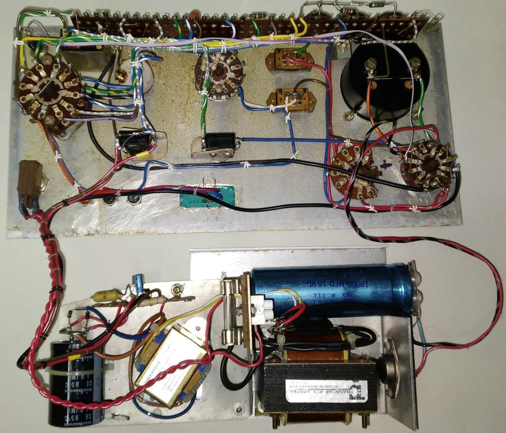  |
The photos show my own (now very old) tester, which is slightly different from the one presented here. It is not as comprehensive, and cannot do some of the neat things included in the new design. Click on an image to see a full-sized version (opens in a new window).
The upper picture shows the internals of the tester. The two power transformers are clearly visible, along with the regulator (far right) and main filter cap. The switching is all on the front panel, and consists mainly of rotary switches. The sharp eyed may be able to see a relay hiding at the top left of the panel. This was used because I could not get hold of a suitable push button switch when I built the tester, so the extra switching was obtained with the relay. This unit is now almost 50 years old, and is still going strong. I have had to fix it a couple of times, with one 'fix' being to replace the valve high voltage buffer with a transistor, and the regulator also failed once. You have to love the idea of using a valve in a transistor tester, but when it was built high voltage transistors didn't exist. The valve was a 12AU7 with both sections in parallel, used as a cathode follower. The switching has never caused a problem, but unlike the new design, this one uses trimpots for calibration. These need the occasional tweak to regain accuracy, but as seen in the circuits, this has been completely avoided with the new design (and a good thing too). Again, when the unit was built 1% resistors were virtually unobtainable, and the standard tolerance I had available at the time was 5%. The tag strip I used to mount all the resistors and trimpots on is visible at the top of the photo, but this requires far too much wiring. The new design requires very little - just a few interconnects here and there between the switches, with the resistors (other than those with high dissipation) wired directly to each switch.
The second photo shows the front of the unit, which was hand lettered using Letraset 'rub-on' lettering, and sprayed with clear lacquer. It has lasted rather well all things considered. If building the new unit, I suggest that you use a ZIF socket (or a transistor socket if you can get one - mine had one but it was a retro-fit) for the small signal transistors, and use binding post/ banana sockets for leads to connect to power devices. Don't use the simple banana sockets like I did - you will regret it because they are a pain if you want to use double ended clip leads. My unit has just received an upgrade - A ZIF (zero insertion force) socket wired E-B-C-E-B, which allows any of the three possible transistor pinouts to be used. This is shown in the new photo (Apr 2023). The binding posts allow you much greater flexibility when using the tester, and with flying leads you will be able to test transistors while still mounted on the heatsink (they must not remain connected to the rest of the circuit, though - this is NOT an in-circuit tester). |
Happy transistor testing. You won't use it every day, but when you need to perform a proper test on a power transistor, you won't regret the time spent building it.
| Main Index
Projects Index |