
|
|
| Elliott Sound Products | Project 261 |
This project is intended to provide the details of a current sensing system for fixed power tools. It's not intended for use with portable tools, but it can be used this way (See Fig. 7). The circuitry is very simple, and should give many years of reliable service. The part most likely to fail within a foreseeable time frame is the power supply. Although these will always be checked for operation when the systems are installed, they are electrically complex and are often the 'weak link' in all modern electronics.
This current detector is designed to sense when a machine draws power, and it operates a warning lamp (and optional audible warning) when the machine is turned on. There's also a timer, designed to keep the alert system on for 5 to 30 seconds after power is turned off. This is sufficient time for most machines (e.g. table saws, jointers, etc.) to stop. The design shown is suitable for machines drawing up to 15A (3,450W) but can be adapted quite easily for higher current (including 3-phase). There's also provision for a blast gate connection (normally open contacts) for workshops equipped with a central vacuum system. If blast gates are used, it's assumed that they will be motorised, having remote activation via external contacts.
Several of these are in operation at the Men's Shed that I frequent, and they replaced units that had been made using commercial current detectors and timers. While the commercial module approach seems like a good idea, it's an expensive way to accomplish a very simple task. Commercial timers are commonly DIN rail mounting, which is a serious nuisance, and without the datasheet, wiring and setup are between difficult and impossible.
Other systems have been described that (essentially) perform much the same job, but IMO using a PIC microcontroller (plus a dual opamp and many other parts) is overkill for such a simple function. There are several other current detectors shown on the ESP website, but this one is dedicated for the task. Note that if you have a stand-alone vacuum system, this unit can drive a power relay to switch it on and off. The warning lamp is a requirement at the Men's Shed, but if you don't need it you don't have to add it.
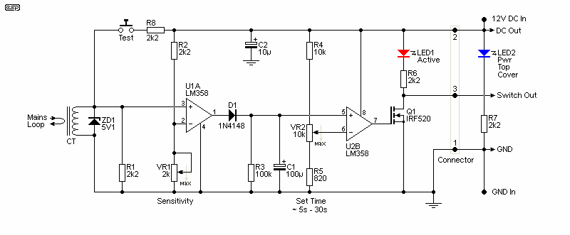
Motor current is sensed by a current transformer (CT), which has a single 'turn' of either the Active or Neutral to the mains output. The CT's output is rectified and clamped by a single 5.1V zener diode. The signal is clamped to 5.1V to prevent gross saturation and/ or the generation of dangerous voltage at the output of the CT. The original circuits I built used a bridge rectifier at the CT's output (as seen in Fig. 2), but this was deemed needlessly complex for such a simple function. It's only a saving of 4 cheap diodes, but they still have to be mounted and take up valuable space on the small Veroboard layout.
The resulting signal is amplified by U1A (LM358 opamp), configured as a comparator, with the sensitivity set using VR1. The output of the first comparator charges a capacitor (C1) via a diode. The reference voltage for U1A is set by VR1 (sensitivity control). U1B is also configured as a comparator, having a variable reference voltage derived from the 'Set Time' trimpot. When the voltage across C2 falls below the reference voltage, the output goes to 0V (GND), turning off the output MOSFET.
The MOSFET is selected to be able to supply any typical load, and it can deliver in excess of 1A to the warning alarm 'head' unit. Two LEDs are provided on the main unit, one indicating that power is available (front panel) and the other showing that the system is active (on the control board). If you know that the load current will be less than 200mA, Q1 can be a 2N7000 MOSFET. There's a lot to be said for using a higher power device though, as that provides greater flexibility. The IRF520 is rated for 100V and 9.2A, and they are both very common everywhere and also cheap. You will likely find that a less powerful MOSFET may cost more! You can use a larger MOSFET if you have them on hand.
A 'Test' push-button is also provided, allowing the user to test the system and set the delay time without having to power the machine on and off repeatedly. The remote 'head' unit will have a lamp (usually red) and an optional audible beeper is needed for very quiet machines such as jointers. The 'Test' button is connected to the input stage to ensure that the timing is predictable between 'test' and 'operate' conditions. Note that the timer starts when the 'Test' button is released.
The remote unit also has an indicator to show that power is on and the system is operational. It is the user's responsibility to ensure that the system is operational before using the machine. Even though 12V power may be present (meaning that blue LED is on), it must be verified that the green remote lamp is on, and the red lamp comes on when the machine is powered on. The sensitivity trimpot lets you adjust the detection threshold, as some machines draw 'residual' current even when not running.
The current sensor is a current transformer (CT), a device specifically intended for measuring/ monitoring current in a wire. The active lead is fed through the hole in the middle, with its insulation intact. Only one pass through the centre is needed. The CT is used outside of its normal operating range (it's rated for 5A), but that's not a problem because it's used to monitor the current, and the amount of current is not important - provided it's above the threshold set with VR1 (sensitivity). This is included because some power tools draw current (not much though) even when not running, to power the switching system, any lamps, and/ or 'SawStop' systems (if fitted). The sensitivity control lets you adjust the system to ignore 'power off' current.
When current flows, the output of the CT is rectified and clamped by ZD1. R1 (2.2k) is included to ensure that Pin.3 of U1A is not 'floating'. U1A provides maximum gain as a comparator, sufficient to drive the output into a 0-10V (approx) square wave. The reference voltage is set with the sensitivity control (VR1). The output from the first comparator is used to charge C1 (100μF) via diode D1.
When power is interrupted to the machine, C1 discharges via R3 (100k), and gradually falls toward zero. After around 23 seconds the voltage across C1 has fallen to 1V. The voltage across C1 is compared to the voltage at the wiper of VR2 (the timer reference voltage). This can be adjusted from 486mV up to 6.25V, allowing the time to be set between ~5 to 30 seconds. U1B is a comparator, and the output is high (around 10V) whenever the voltage on Pin.5 is greater than the voltage on Pin.6.
The output of U1B feeds the gate of the MOSFET, which switches the external 'head unit' on and off. It's capable of supplying over 1A without a heatsink. The load should not be greater than 4A, but will most often be limited to much less by the power supply. LED warning lamps generally don't draw much over 150mA.
The detector/ timer module is mounted on a plate with screw terminals for DC in and head unit out. Be very careful with the DC input. If it's connected in reverse (positive to negative, negative to positive) the unit or the power supply may be damaged. In all cases, the polarities are indicated next to the terminals.
The test button is provided so the time can be set without having to power the machine on and off. First, you need to use a stopwatch to determine how long the machine keeps spinning after power is turned off. If it takes (say) 12 seconds, the timer should be adjusted for about 13-14 seconds using the timing trimpot (VR2). Press the test button, and time the on-board LED, waiting for it to go off after the test button is released. Adjust VR2 until the LED stays on for the desired time.
It's better for the warning system to stay on for a bit longer than it takes for the machine to stop than for it to turn off while the blade is still moving.
The time delay is fairly accurate and repeatable. It will vary slightly with temperature, and may need to be adjusted every so often as the circuit ages. The recommended calibration interval is about 12 months, or if it's noticed that the time is longer or shorter than expected. Simple circuitry means lower precision than you'd get with a PIC or Arduino, but there no programming and it's more than acceptable for the intended use. Common sense is also a requirement, and that is needed with all power tools. The lamp is only a warning, and when it goes out that's not an invitation to do something that you'll regret moments later!
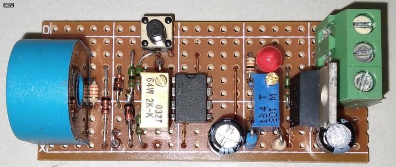
The photo of the control board is provided for reference (this is an early board that has a few extra parts that have been removed from the Fig. 1 circuit). The individual resistors, diodes, etc. are not referenced here. The current transformer is the device on the left, followed by the (now removed) diode bridge and clamping zener diode. The test switch is at the very top of the picture. Directly below that is the screwdriver adjusted sensitivity control. The opamp (operational amplifier) is the rectangular device with 8 leads. Pin.1 is at the top-left.
The timing capacitor is next, at the bottom of the board. The time-set trimpot is the blue rectangular device, and the small screw lets you set the time delay. The on-board LED is above the trimpot. The switching MOSFET is next, and the terminal block is at the extreme top-right. The top terminal is +12V DC, the switched output is in the middle, with the -12V ('GND') terminal at the bottom.
For the warning lamp, a flashing/ strobing/ rotating lamp can be used but may be too distracting. In addition, a green 'ring' lamp with 6 LEDs is used at the base of the warning lamp to show that the warning lamp is connected and is provided with 12V power. If the green indicator is not illuminated, that means that the connector may have been unplugged or the cable has been damaged.
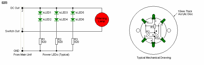
The green ring light is easily fabricated using a ring turned from 10mm clear acrylic, drilled from the inside for the six LEDs. You can add top and bottom sections (above and below the clear acrylic ring) if you choose, but these are optional. The resistor and LED leads are shown in 'diagram' form, but they will typically be arranged as a circle around the inner edge of the ring. Because the ring is not overly bright, there's no reason to turn it off when the red light is on.
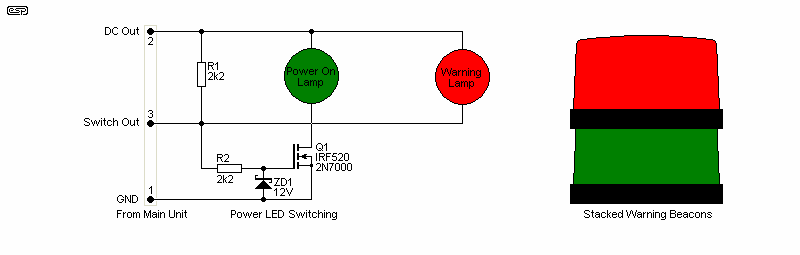
LED 'beacon' lamps (typically intended for boating) are a good alternative to the 'standard' lamp with it's green ring light. They are usually quite bright, but many are designed to flash, which is very distracting (a distraction is the last thing anyone wants near a power saw). A bit of extra circuitry is used to turn off the green lamp when the red lamp is activated, but this is easily added. The IRF520 specified is overkill, but they're cheap and available anywhere. A modified beacon lamp draws about 100mA (1.2W nominal), and this is easily handled by a 2N7000 if you have them on hand.
To disable the flasher circuitry, you simply need to locate the switching transistor/ MOSFET on the lamp's PCB and short the collector to emitter (or drain to source). You could go further and remove the parts, but that's far more trouble than it's worth. In some cases you'll find a pair of pads intended for a jumper platform, so either install the jumper pins to have optional flashing red (no jumper installed), or short the pads together. Note that some ingenuity is needed to stack the two lamps. You might be able to get a beacon with both red and green lamps in a column if you think that's easier (IMO it's probably not, but I have good machining capabilities in my home workshop).
The above are examples, and you may choose to use something different. Any LED lamp style is suitable, arranged how you want it to look. The lower current rating and life span of LEDs is ideal, and the use of incandescent lamps is not recommended. Existing incandescent housings can be retro-fitted with an LED array, but note that it becomes polarity sensitive if you make that change. There are LED 'bulbs' that can replace an incandescent lamp if you want the minimum fuss for the change.
The wiring is straightforward, and a complete diagram is shown next. Take particular care with the earth lead, and ensure that both wires into the terminal pass all the way through so each has two screws. Insulate all mains connections as needed so the bare wires cannot be touched.
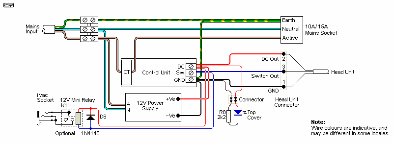
The active or neutral lead to the external machine has a single loop through the current transformer. Convention is to use the active, but the neutral carries the same current and is equally effective. All mains wiring must be with mains rated cable, and intended for the maximum current drawn.
No part of the low voltage wiring should be routed next to mains wiring or terminals. The low voltage circuits are fully isolated from the mains (other than earth/ ground), and there is no accessible metalwork that requires a mains earth - unless a metal enclosure is used. A connection between ground and the power supply negative is not required, but it is recommended. Should the PSU suffer an electrical breakdown, without the ground connection parts that should be safe may become dangerous.
The 12V mini-relay and 3.5mm socket are optional. If used, these can replace the suction system's current sensor, and only a cable is needed between the current detector and blast gate (typically using 3.5mm phone plugs). This eliminates a sensor and its power supply, and frees up a unit address when RF (radio frequency) encoded transmitters are used (limited addresses are normally available on a system). Note that the relay must be a 'small-signal' (low current) type, as the current from the blast gate system is low and a power relay may not make reliable contact.
The front panel LED indicator and its resistor will typically be attached to the panel using a suitable adhesive, and anchored so that it cannot come free inside the box. A photo of a wired unit is shown next so you can see what's involved. The connector is a 3-pin type with a screw-down retainer to ensure that it can't detach if the unit is moved. The main unit (the detector/ timer) has a female connector, and the remote lamp has a fixed lead with the male plug at the end. Take care of the cable and connector - the cable should be long enough to reach the detector unit without being so long as to drag on the floor where it may be damaged.
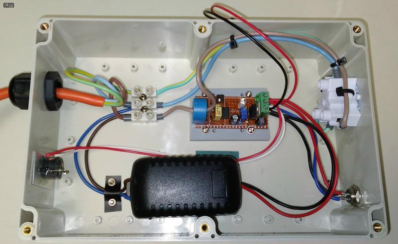
The mains input is at the top left (via the cable gland), with the three leads to the terminal block. The mains output socket is at the top right, with the active lead passing through the current transformer. The power supply (PSU) is the black case, modified so the mains pins are removed and replaced by threaded inserts. An insulator is attached internally so the screws cannot make contact with the circuit board. The controller is above the PSU, and the red and black leads disappearing out of the case have the connector for the front panel LED. The optional blast gate socket and relay are at the bottom left, with the output to the warning lamp at the bottom right. The connector you use just needs to have three pins, and the wiring is up to you. I suggest that Pin.1 is negative (ground, common), Pin.2 should be +12V DC and Pin.3 will be the switched output. Note that the unit shown does not have the connection between ground and the PSU's negative output.
The sensitivity will need to be adjusted depending on the machine. Some table saws draw enough current when turned off to trigger the monitor, so the sensitivity control needs to be adjusted until the on-board LED goes out. Set the time for the minimum, and adjust the trimpot slowly. When you find the critical current setting, turn the trimpot's adjusting screw 2 full turns anti-clockwise. Power on the saw and verify that the LED comes on instantly. Ensure that it remains on with no load (not cutting anything).
The timer is set so that the red LED goes out about 1-2 seconds after the blade has stopped. Clockwise rotation increases the time.
Trimpots:
Sensitivity clockwise – more sensitive
Time clockwise – longer delay
Note that the screws that hold the control board to the plastic mount must not be over-tightened. Doing so risks cracking the board and causing the circuit to malfunction. The four screws may or may not have plastic washers (depending on the clearance between the screw and the board), and just need to be snug, not tight.
After installation, the PCB mounting screws can be locked in position with a small dab of nail polish or other non-conducting lacquer.
Also shown here is the relay that can be added to activate a blast gate or suction system. This is a trivial upgrade, and removes the need for an additional current sensor for the suction system. The vacuum system blast gates usually have provision for a contact closure to activate the blast gate. If used, the relay coil connects to the positive 12V supply and the 'Switch' output, with a diode across the relay (cathode to +ve supply). This is shown in Fig. 5.
The 'NO' (normally open) contacts are then wired to a suitable connector (typically a 3.5mm phone jack) so a 2-core cable can be run to the blast gate. The blast gate must be set for the 'Closed' position, and when the external relay contacts close, the blast gate will open. See the system setup guide for the system you use for details.
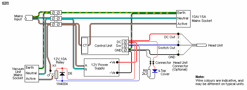
In some cases, you won't have a central vacuum system with blast gates, but will hook up a single vacuum system to the unit. The wiring for this is shown above, and in this case the warning lamp is optional. The small relay is replaced by a mains-rated 10A relay, and note that the diode is upgraded to a 1N4004 or similar. The time delay for the vacuum unit is adjusted in the same way as for a warning lamp, as is sensitivity. This version can be portable, and moved around as needed so the vacuum system is turned on by whatever power tool is in use.
The relay has to be rated for the current drawn by your vacuum system, but not less than 10A regardless. Only the normally open (NO) contacts are used, and the relay coil is 12V DC. The vacuum will start as soon as the tool is powered on, and remains on until the timer expires.
Note that the combined current drawn by the power tool and the vacuum system is limited to the current rating of the input cable. In 230V countries this can be either 10A or 15A, and in most 120V countries it's 20A. You need to check your local wiring rules to determine what is acceptable. If you have an especially powerful tool or vacuum system that draws more than the allowable current, you can have two input cables, which must be wired to different mains circuits. For example, if both the tool and the vacuum system draw 10A, that's a total of 20A, and a 16A breaker will trip. By splitting the load across two mains circuits (each with its own circuit breaker), you can run both at full current.
Note: This is a very flexible design, but it is designed specifically for fixed power tools. Because of the box housing the electronics it's not really suitable for portable tools, due to the risk of damage to the enclosure. This could expose live mains wiring, posing a high risk of electric shock. If the controller box is in a fixed location this limitation is mitigated (to some degree).
In a workshop, a power relay to turn on a vacuum system is easily added, or the small signal relay can be used to activate blast gates used with a large central vacuum system. I haven't even tried to include the wiring for every possibility, because there are quite a few (and no doubt some I haven't thought of). While the primary purpose when I started the design was to activate warning lights, it's capable of much more.
As I'm sure people have noticed, this is not an audio project, but if you are an avid speaker-builder then it can be put to good use. Although it's really intended for noisy workshops and fixed (bench) power tools, it will also work as a vacuum controller with hand-held power saws and the like. The control box must be mounted securely so it isn't dragged around the floor, where damage is inevitable. If it's used only as a vacuum controller, the lights can be omitted (along with the connector), and a power relay is wired in place of the lights (remember to include the reverse diode).
In some cases you might prefer that the vacuum activation relay is remote from the detector. If that's the case, you only need a single pair control cable (+Ve Supply and Switched Output). The relay for the vacuum system can be some distance from the detector unit, and this may prove more convenient in some workshop setups.
There are no references, as this is an original design based on other current detectors that are shown on the ESP website.
 Main Index
Projects Index Main Index
Projects Index
|