

|
| Elliott Sound Products | Project 250 |
There are several reasons that you might want to test inductors to find their saturation current. In a switchmode supply (SMPS), you must avoid saturation or failure of the switching transistor (almost always a MOSFET) is probable. When a magnetic core is fully saturated, it effectively ceases to exist. When in full saturation, the magnetic flux in the core cannot increase any further, and if there's no change in flux, there's almost nothing to limit the current.
Of course, there's still the inductance of the windings (which now effectively have an air core), but the inductance will generally be reduced by a factor of 10-100 times (perhaps more) with a fully saturated core. Power inductors have a maximum rated current, and that's determined by the core material, its temperature, and winding resistance. A tiny ferrite core will saturate at a low current, and the gauge of wire used will be suitable for the rated current.
You won't find a 10A inductor with a 100Ω winding resistance, nor will you find a 100mA inductor with a few milliohms of winding resistance. The exact resistance depends on many factors - it should be as low as possible to minimise I²R losses, but ultimately it will be a compromise. The power dissipated in the winding depends on the average current, and it varies with the core size.
A 10mm diameter core can't be expected to dissipate several watts, but a large power inductor may easily handle that much. Higher than ideal winding resistance reduces the Q of an inductor, causes unacceptable losses and means the inductor runs hot. With some ferrite cores, an elevated temperature means that the inductance changes and the inductor may saturate at a lower current.
In several places on the ESP website I've noted that inductors are the worst passive components known. Resistors have a tiny amount of 'stray' inductance and capacitance, while capacitors have very small amounts of resistance (primarily ESR - equivalent series resistance) and inductance, the latter based mainly on their physical length. By comparison, inductors have significant (and generally easily measured) resistance, inter-winding capacitance and leakage inductance (caused by magnetic flux that 'escapes' from the core if one is used). You need 'special' measurement techniques to measure the self-resonant frequency of a capacitor (it's easy, but many people get it wrong), and it may be easy to measure it with many inductors. An ideal passive component has none of the other characteristics, and real resistors and capacitors come close at moderate frequencies. Inductors aren't close at any frequency, although silver-plated air-cored RF inductors are probably as near as you'll get.
Used within ratings, resistors and capacitors rarely cause issues of value drift or other changes, but inductors will change their resistance with temperature (due to the tempco of the wire), and when a core is introduced, the inductor becomes application-specific. There are application-specific resistors and capacitors too, but they can still generally be used in circuits that don't require their particular/ peculiar characteristics (high pulse current, high voltage, etc.). If you use an inductor in the wrong way you risk anything from poor performance to releasing the 'magic smoke'.
Note: The two circuits I recommend are shown in Fig 3.1 and Fig 3.2. These require the use of a digital scope with single-sweep capability (almost all have it). If you don't know how to use the single-sweep function, consult the manual for your scope and it should tell you everything you need to know.
It's interesting to note that almost all of the designs you'll see on the Net use continuous pulsing, rather than the single 'on demand' pulse arrangement I recommend. I'm unsure of the reason, but I suspect that it's assumed that most people won't have a digital scope, and/or don't know how to use the single sweep function. I've assumed the opposite - (working) analogue scopes are now hard to find, and single sweep operation with a digital scope is easy to use. You may need to read the manual if you've never used single sweep, but that's not too hard. 
There are several saturation tester circuits described on-line, some well thought out, others not so much. There are many requirements for saturation testing, not the least of which is protection of the DUT (device under test) and the tester itself. If the current is allowed to increase well beyond the rating for the DUT, it may be damaged. Likewise the switching MOSFET in the tester may be damaged by excess current.
Most inductors that will be used in medium-high power SMPS or Class-D amplifiers will have to handle up to 10A or more. If their winding resistance is as low as it should be (around 50mΩ for 5W dissipation) all is likely to be ok, but not all are designed or specified to handle the current.
The next problem is the core. It may be expected to handle a flux density that exceeds the ratings for the core material, meaning it will saturate. There are two main parameters for a core material - permeability and maximum flux density. Both depend on the core material. Permeability (or more correctly relative permeability) is a measure of how well the material carries magnetic flux compared to the reference - free space or air.
Testing high-current inductors is always a challenge, because you need to be able to provide the high current needed for saturation tests. This can be 40-50A in some cases, although the duration is very short. That means heavy gauge wiring, a good storage bank (capacitors) and a power supply that can keep everything powered without collapsing. It should be able to deliver at least 2.5A (continuous) so it can recharge the capacitor bank after a test cycle. The design goal for the tester described is up to 50A peak current.
The basics of inductors are simple if we take away their flaws. An ideal inductor of 1H with 1V applied to it will allow the current to rise at 1A/second. If power is maintained, the current keeps rising at 1A/s, ultimately limited by the resistance of the coil. An ideal inductor has no resistance, so the ultimate current is infinite (after an infinite time has passed). Of course this doesn't happen at all. We have real parts, not 'ideal' ones. However, this basic understanding is essential to allow you to understand the processes at work.
Most people are acquainted with the idea of a resistor/ capacitor time-constant ( tc=R×C ), but inductors also have a time constant. With inductors, the formula is tc=L/R. The resistance is a combination of internal and external resistances, with the internal resistance creating potentially large errors. When current is applied, after one time constant it will have risen to 63.2% of the maximum (determined by the voltage and resistance). For example, a 100μH inductor with 10Ω series resistance will reach 623mA in 10μs with a 10V supply. It's interesting to note that even simulated inductors (gyrators) have internal resistance. It's an inescapable flaw with all inductors.

The only inductor that can behave as shown by the green trace will be air-cored (or have an infinite magnetic core, which might prove difficult to find). With a 120μH inductor, the current will be 10A after 100μs (with zero resistance). In reality, the limit is always set by the winding resistance if the core doesn't saturate. If the coil has 100mΩ of resistance, the ultimate current is limited to 10A with a 1.2V supply, but the curve will not be linear. After 100μs, the current won't be 1A, it will only get to 960mA, because the voltage across the coil is reduced due to the winding resistance. This is always an 'external' parameter - the winding resistance doesn't affect the inductance, but it does affect the voltage across the inductor. Any real (air cored)inductor can be approximated by using an 'ideal' inductor with the coil resistance as an external component. This is important for passive speaker crossover networks for example.
When a core is introduced, the rated inductance is only available while the core remains unsaturated, meaning that the increasing magnetic field strength causes a corresponding increase of the magnetic flux in the core. This relationship is shown in the next section. The onset of saturation of a 188μH inductor (red trace) is shown, along with the current path if it didn't saturate (thin red line). Once saturation occurs, it only gets worse if current is maintained, until it's limited by the applied voltage and the winding resistance. The maximum safe working current for the inductor shown by the red trace would be about 4.5-5A. In case you're wondering, 188μH was chosen so that the two graphs extended to 100μs and 10A peak.
Not all inductors are saturation-limited. If used at very high frequencies (e.g. over 250kHz) the major source of losses could be the ferrite material itself. This can be determined from the datasheet for the grade of ferrite used (if available), but if you have an inductor that runs hot but is nowhere near saturation and has low winding resistance, then the operating frequency is probably too high.
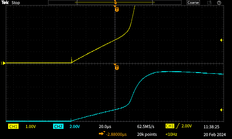
The two traces above were taken from a 'junk box' inductor that came out of a high-power LED lamp PSU. Based on the formula shown below, the upper trace shows the current to be 20A after 60μs, meaning that the inductance is 36μH. The maximum current is about 25A at the onset of saturation. The lower trace (2V/ division!) shows what happened when I kept the test switch closed for around 250ms (this test was done before I had wired up the timer circuit). The inductor saturates heavily and the current rises to about 44A before the reservoir cap discharges too far. I used a 10,000μF (10mF) cap, charged to 12V from a bench supply. The maximum usable current is around 30A, somewhat less than the ideal. That shows that 10mF is insufficient if high current is needed, as it will drop by 1V in the first 1ms.
This test could not have been any simpler. I used a pushbutton switch to connect the inductor, and the current was monitored across a 100mΩ, 5W resistor. Most of my initial reservations about using a 5W resistor were proven to be out of order - it handles the current easily. It might be different if I pushed it to 100A or more, but that's way beyond anything I need to test.
Relative permeability (μr is the ratio between the material's permeability vs. that of free space. It's commonly referred to as just permeability (μ), with the 'relative' bit taken for granted. For iron and ferrite based materials, the (maximum) relative permeability ranges from 100,000 (Permalloy at 0.5T field strength) down to around 20 for various iron powder and/ or ferrite materials. The allowable field strength ranges from 1mT (milli-Tesla) up to 0.5T.
Ferrites in particular can be very fussy. Not only is the permeability subject to field strength, but also frequency. Some are usable at 50Hz, but others may require the frequency to be at least 10kHz. Many will complain bitterly if they are operated above their maximum rated frequency, which ranges from 10kHz up to 500MHz. The frequency is determined (at least in part) by the material's particle size. Large particles will suffer high eddy-current losses at high frequencies. For the same reason, mains power transformers (and inductors) use laminated steel cores, and thinner laminations allow operation at higher frequencies.
The BH curve is pretty well known, and it describes the flux density within a material vs. the applied magnetic field strength derived from the coil. The important parts are shown in the drawing. Coercivity is a measure of the resistance of a magnetic material to be demagnetised after saturation, and remanence is the amount of residual magnetism after the magnetising force has been removed. Both of these should be low for core materials, as that implies a lower core loss (although other factors are also involved).
Another parameter for ferrites (and some other core types) is the Curie temperature. Permeability is at its maximum just below the Curie temperature, but above that it falls dramatically. All cores will normally be operated well below the Curie temperature, largely because it's so high that insulation will be damaged (and solder joints seriously weakened). Expect somewhere between 200-300°C. Despite it being so high, it's quoted in most magnetic core datasheets even though it should never even be approached in a circuit.
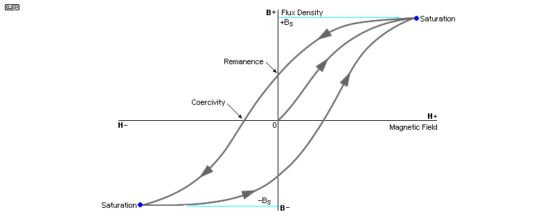
We are primarily interested in one parameter - saturation (indicated as Bs). The other parameters are essential for the designer, but not the end-user. High remanence is essential for permanent magnets, and these use 'hard' magnetic materials. This doesn't mean physically hard (although that's true of most magnets), it means they are magnetically hard, so retain magnetism (high remanence). High remanence and high coercivity usually go hand-in-hand. Core materials are described as 'soft' (magnetically), and again most are physically hard.
A common 'trick' (which is perfectly legitimate) is to include an air gap in the magnetic circuit. This doesn't prevent saturation, but by reducing the effective permeability it means that the coil can produce more flux before the core saturates. Some magnetic materials have a 'distributed' air gap (especially iron powder ceramics), where the magnetic material is not homogenous, but distributed within a non-magnetic filler material.
The range of ferrites and powdered iron cores is staggering. They range from toroids to E-I format, and include various 'pot' core designs that enclose the windings within the core itself. There are also planar cores, designed to use coils etched into a PCB. Mouser lists over 3,000 different ferrite products, and then there's the proliferation of bobbins, clamps and other accessories needed. This is a small subset of the types available from major manufacturers!
None of this is of great interest when you have a coil that you need to characterise. If it's not indicated on the coil, you need to be able to determine the inductance, which may or may not be measurable with an inductance meter. More importantly, you need to be able to determine the saturation current. If you buy from a reputable supplier the details will be available, but if it's reclaimed from something else or bought from eBay or Amazon, the details may be missing, lacking the info you need, or completely wrong.
If you have an unknown inductor and want to know its inductance, simply place a cap in series and feed it from your audio oscillator. Adjust the frequency until you get a distinct peak - that's resonance. Knowing the frequency lets you work out the inductance. For example, if you used a 10nF cap and resonance is at 64kHz, use the formula ...
L = 1 / ( 2π² × f² × C )
L = 1 / ( 2π² × 64k² × 10n ) = 618μH
The formula is derived from the formula we use to calculate the resonant frequency ...
f = 1 / ( 2π × √L×C )
If you work out the formula above with the inductance you calculate, you should get the frequency you started with. Always be careful with a series L/C network. Make sure that the circuit is driven from a 'sensible' impedance, ideally no less than 10Ω. With a low impedance source, it's very easy to generate very high voltages, and the amplifier (if used) will suffer due to high current. A series resonant circuit is effectively a short-circuit at resonance, and current is limited only by the series resistance in the source and the inductor itself.
Of course you can use an LCR meter as well, but you'll often find that it gives you the wrong answer. If a coil has a high resistance, an LCR meter may show a surprisingly large error, but you probably won't know that. It's not like the meter will have an indicator to tell you that the answer it just gave is incorrect. With some, you can set the frequency, and if you see the inductance change whenever you change the frequency, you know you're in trouble. The method described above always works, but it's a lot of messing around.
In theory this is dead easy. Pump a high enough current into the inductor, and measure the current risetime. You'll use a pulsed current source, and the pulses must be wide enough to cover the range of coils you want to test, but not so wide that they cause failure of the DUT, the switching MOSFET or your power supply. Most saturation testers do exactly that, with changes mainly confined to switching pulse generation. Some use a current cut-off, while others don't. This project uses a timed pulse, with no 'over-current' detection.
There is no power supply circuit as part of this project, as it's designed to be used with an external PSU, which must be capable of working into a shorted output. That means it should have good current limiting to protect itself. The supply will see close to a dead short each time the storage capacitor is discharged fully. Fortunately, this won't happen (most of the time at least) if you start with a low pulse width and work your way up to a width that just causes visible saturation.
Adding a power supply would mean more parts and cost, and as something that won't be used every day, adding a PSU wasn't considered viable. The bench supply needs to be able to provide around 5A or so at 12V, but most of the time it will be idling. The capacitor bank provides the energy storage needed for pulsing the inductor at up to 40-50A, and the external supply only needs to be able to recharge the caps quickly enough to let you take measurements. If you use the single-pulse timer circuit, a 1A external supply will be enough, but it will be overloaded when the caps are charged for the first time. A 2A supply can charge 20mF (20,000μF) fully in about 120ms ...
t = V × C / I
t = 12 × 20m / 2 = 120ms
In most cases, a 1ms pulse will be sufficient. After voltage is applied, the current increases linearly until the core saturates, after which it becomes non-linear and increases rapidly. By knowing the applied voltage and measuring the time taken to reach a particular current before saturation, you can also determine the inductance. This is likely to be more accurate than an inductance tester as found in an LCR (inductance, capacitance & resistance) meter.
L = V × Δt / ΔI Also written as ...
L = V × dt / dI
Delta (Δ) simply means 'change'. If the applied voltage is 12V, the peak (or reference) current is 20A and it takes 60μs to get there (see Fig. 1.2), the inductance is ...
L = 12 × 60μ / 20 = 36μH
However, this may not be completely accurate because the voltage across the inductor will always be less than the supply voltage. There is a voltage drop across the coil due to its resistance, and the shunt used to measure the current will also drop some voltage, as will the MOSFET. If there's a 100mΩ winding resistance and a 100mΩ shunt, you 'lose' 100mV/A across each, so the supply voltage isn't 12V - the average over the sample period is closer to 11V. If we use that in the formula we get an inductance of 33μH. We can safely say that the real inductance is somewhere between the two.
Importantly, this doesn't matter that much. Inductors are already the worst electronic component known, and no one expects them to be particularly accurate. The only ones that can be corrected to be within (say) 1% are air-cored coils or specialty coils used in equalisation circuits or for radio frequency applications. Because there is no core, an air-cored inductor doesn't change its inductance with temperature, current or whim. Of course it will also be much larger than a coil with a core, and it will have significant winding resistance.
If you wanted to, you could also estimate the inductance beyond saturation, by using the same parameters (Δt and ΔI) on the slope after the core saturates. I doubt that this will ever be useful, but it can be done. Using the blue trace in Fig. 1.2, beyond saturation the current rises by 20A in about 8μs. That means that the inductance has fallen from ~36μH to ~4.8μH.
The timer I used is crude but effective. With the values shown it's adjustable from ~13μs up to 1.6ms. The output is squared up by the two 2N7000 MOSFETs, and while there's a little bit of sag as C3 discharges, the gate voltage for Q6 is maintained above 10V for the full duration of the pulse. C1 only takes about 200ms to charge, so it's faster than you'll be able to set up for another test. I decided against a repeating timer, because you should use a scope with single sweep capabilities to capture the waveform for analysis. If you need a repeating timer, see Fig. 3.4.
One thing that's critical for the proper evaluation of an inductor is the time between pulses. If they are too close together (e.g. if you were to use an oscillator that's too fast) the inductor current may not fall to zero between pulses, and it will operate in continuous conduction mode (CCM). For evaluation, the coil needs to operate in discontinuous current mode (DCM), with the current falling to zero between test cycles. In most cases this will not be a problem, even if you were to pulse the coil at (say) 20Hz. In the interests of keeping dissipation in all parts of the tester low (and not punishing the power supply), a low repetition rate is preferable. This is 'automatic' when you have to press the 'Pulse' button to take a measurement.
A current limiter is possible, but it is harder to implement and requires quite a few more parts. With inductors designed for SMPS, the entire measurement can be over in only a couple of hundred microseconds. That means that a current detector has to be fast, and cut off the current as soon as it exceeds the preset maximum. Rather than mess around with a comparatively complex current cutout, you adjust the timer instead. Start at minimum time (about 13μs), and advance the time until saturation is visible. It will take a few tests to get you there, but a test sequence only takes a few seconds.
The only other parts needed are a few passives (resistors and capacitors), two small-signal MOSFETs, two general purpose BJTs, the switching MOSFET and a current shunt. You also need a power diode across the inductor, plus a 1N4004 or similar. The biggest choice you have to make is the switching MOSFET. The instantaneous current can be up to 40A, so you have to provide a significant capacitance so the voltage doesn't collapse during the test. The peak saturation current may only last for a few hundred microseconds, but if you draw 40A for too long the voltage will collapse to nothing (and your power supply won't be at all happy).
The capacitor bank might be the most expensive part of the project (along with the 10-turn wirewound pot). You could use a Li-Ion battery pack (3 x 18650 cells in series), but they can't be protected and will cost more than capacitors. You only need a cap voltage rating of 16V, and suitable caps shouldn't cost more than ~AU$6.00 each for 10,000μF (10mF) types. You need at least two. Any combination of capacitors that you have to hand will be fine, provided you get at least 2mF. I ended up using 8 × 3,300μF low-ESR caps - a total of 26.4mF (26,400μF). I have verified that even with basic wiring I can get well over 60A pulse current, and all tests performed thus far have shown that the available current is satisfactory.
The diode in parallel with your DUT has to be able to carry the peak current that was put through the inductor. If you pulse at 30A (without saturation), the diode will also have to pass at least 30A, but it will probably be more. The suggested 1N5404 (or P600G) can handle a non-repetitive peak current of 200A (400A). It doesn't need to be a fast diode because the switching is slow. Of course you can use a high-speed diode if you have one on hand, but check the peak current rating.
An IRF540N MOSFET is rated for 33A continuous or 110A peak, and that's more than sufficient. Because of the very low duty-cycle, it won't even need a heatsink unless you plan to run a test for an extended period. The voltage drop across the MOSFET will be 1.76V at 40A, but in most cases that will be peak saturation current and the voltage loss is insignificant compared to wiring, the current shunt and the coil's winding resistance. If you have something better to hand then by all means use it, as it's not too critical. Of course you can also use a pair of IRF540s in parallel, and get lower Rds-on and reduced power dissipation (each should have its own gate resistor). The alternative is an IRFP4310Z or similar - 100V, 120A (continuous) and less than 6mΩ Rds-on, but far more expensive.
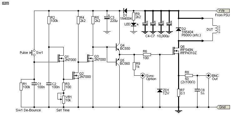
The tester itself is based on Q6, a high-current MOSFET. The 100mΩ shunt resistor is important, as it has to be able to handle up to 60A peak current. My tests have shown that a standard 100mΩ, 5W resistor works just fine, even though they are not really designed for an impulse power of perhaps 160W or more. A more robust solution would be to use a dedicated shunt, or use 4 × 0.1Ω 5W resistors in series/ parallel. While it may seem that a lower resistance would be 'better', this also makes the output lower, and you need to be able to see it on a scope. If you prefer to use a 10mΩ shunt (10mV/A) then feel free to do so.
The optional Sync output will trigger the scope at the instant the Pulse button is pressed. The scope will normally be set for 'external trigger' to use this. It's not essential, but it will make measurements easier because the reference point is fixed. It doesn't have to be a connector - a wire loop you can hook a scope probe onto is just as useful (maybe more so). The trigger output is shown for the other versions as well.
Although you can use an analogue scope it will be very hard to get a reading (see Fig. 3.3). You really need a digital scope because you can set it up for a single sweep, and capture the waveform (as seen in Fig 1.1). The shunt should have low inductance, but most 0.1Ω resistors should be perfectly alright. R8 is shown as 50Ω (2 x 100Ω in parallel) if you think you need a 50Ω output impedance. 100Ω will normally be quite alright, but 50Ω is preferred if you use a BNC-BNC 1:1 cable between the tester and the scope (assuming the use of 50Ω coaxial cable).
The circuit is straightforward, using a very simple timer circuit, buffered by Q4/Q5 as a low-impedance gate drive. The current is monitored across R7, the shunt resistor. When the 'Pulse' switch is pressed, C1 charges instantly, turning on Q1 which passes the charge on C2 to Q2 and the time setting resistors. The output from the Q4/Q5 buffer drives the gate of the switching MOSFET. The output is almost a perfect pulse, because of the high gain of the two MOSFETs. Keep all wiring short for the timer and buffer circuits to ensure a fast risetime (it should be under 1μs). ZD1 and ZD2 are included to protect the gates, which are easily damaged by a static charge. Given the rather nasty load of an inductor, this is cheap insurance.
Perhaps surprisingly, the most critical part of the circuit is the switch! Most standard pushbutton switches have excessive contact bounce, and it may take several attempts to get a clean trace. Mini 'tactile' switches are very good in this respect, and have almost no bounce because they have such a low moving mass. They are one of the few that will give a good result. The circuit can be made to work with a standard pushbutton, but the switch 'conditioning' circuit (Sw1 De-Bounce) is essential to eliminate the contact bounce.
It's fairly basic, but it works well regardless. When the button is pressed, the first contact (however brief) will charge C1, and turn on Q1. Be aware that the instantaneous current will be at least a couple of amps, as the cap has almost no ESR. This is unlikely to cause a problem though. A 'better' de-bounce circuit could have been used, but it would be more complex and more irksome to wire up. A MOSFET is required because the base current of a BJT would 'upset' the timing circuit. C2 then turns on Q2 with the output inverted by Q3 before the pulse is buffered by Q4/Q5. The discharge time for C2 is determined by R3 and VR1, and can be varied from 13μs to about 1.6ms. It can be extended, but that's unlikely to be useful with most of the inductors used in SMPS or Class-D amplifiers.
All high-current wiring needs to be short and thick, and closely spaced to minimise stray inductance. Every 10mm of wire adds about 10nH of stray inductance, but this is reduced with thick wire and close spacing. Using terminals for the high-current test leads is not a good idea, as their resistance may skew the results (and you can't have them too close together). In most cases the stray inductance won't be a major issue as long as you keep the wiring short.
Note the heavy tracks and grounds - these need to be the lowest possible resistance, and should use heavy-gauge wire. The output leads to the DUT should not have any connectors, and will ideally be soldered directly to the inductor. Choose C3-C6 wisely, and aim for the lowest ESR (equivalent series resistance) you can get. Although I've shown 40mF in total, I used 26mF and you may also be able to get away with less (or feel free to use more).
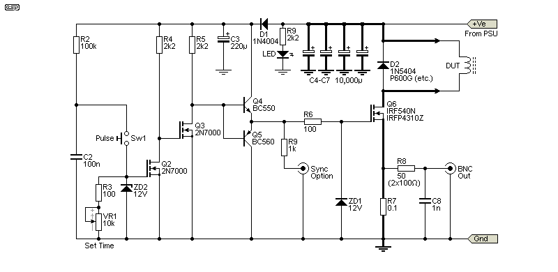
The circuit shown in Fig. 3.2 is the one I built. I employed a miniature tactile switch (shown below) after verifying that it has (almost) no contact bounce. Switching is reliable, but there is very occasional evidence of some contact 'misbehaviour'. Given that my unit won't be used often, if it mangles the trace every so often I can live with that. I know what to expect, and if I see something different I know I have to repeat the test. It only takes a few seconds, and I run several tests of this type anyway. Note that I deliberately didn't change the remaining component designators. The items removed are Q1, R1 and C1 - the rest of the circuit is unchanged. As well as being the version I made, I recommend that you do the same because it's the simplest to set up and use. Note the addition of ZD2 - the gate is vulnerable (mainly during assembly) and it's protected by the zener. It's not needed in the Fig. 3.1 version.
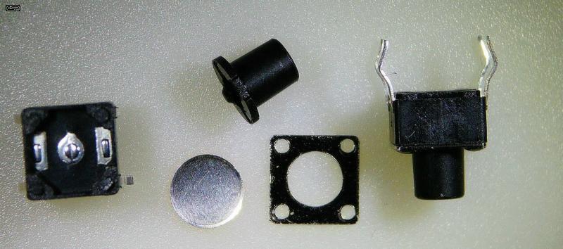
The Mini Tactile Switch is shown above, including one that I dismantled so you can see what's inside. The answer is "not much", just 3 contact points and a tiny concave disc that snaps to the centre contact when pressed by the actuator. The photo of the switch is included so you can see the exact type I used. Many different types of switches are sold as 'tactile', but they are not necessarily equivalent. The defining feature of the one I used is that its moving mass is tiny, and that means there's far less chance of contact bounce. Some other switches might be equally resistant to contact bounce, but I can't test every switch you can buy. I did test several I have to hand, and no others were satisfactory.
In the circuit shown in Fig. 3.2, the maximum current the switch needs to pass is only 120mA, with most tests requiring less (around 30mA for a 65μs pulse). Multiple tests showed switching that was completely reliable. I tested with 100nF and 100Ω, and measured a completely reliable 13μs switching pulse. As with a great many of my personal projects, the switching circuit and gate driver were built on a small piece of Veroboard. Despite the fast switching, the circuit is reasonably tolerant of your wiring, but it should be kept short.
I used a 10-turn pot for VR1 so I can adjust the timing easily. The lower settings will probably be the most-used, for the simple reason that large inductance values capable of high current are not common. However, allowing a measurement period of up to 1.6ms is potentially useful. It remains to be seen how often it gets used of course.
If you think that continuous pulsing is a good idea (which I don't), you can use the following circuit. I've kept most of the designators the same so there's no confusion. The timer/ oscillator uses a CMOS 4584 (or 40106) hex Schmitt trigger, and will pulse at about 24Hz. The minimum time is about 65μs, extended to 1.9ms with VR1 at maximum resistance. The circuit will pulse only for as long as Sw1 is depressed (you could use a toggle switch if you prefer not holding the button).
There are two important changes. Q5 must have a heatsink, and R7 is reduced to 10mΩ to reduce dissipation. Your external power supply has to be able to supply more current, and you may need to replace D2 with a TO220 packaged diode with a heatsink. Because the repetition rate is so much higher than a manual test, everything needs to be more robust and capable of handling higher power levels.
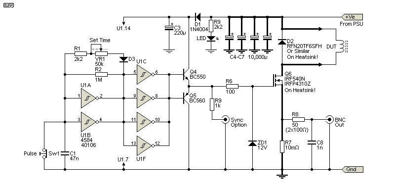
While this certainly looks simpler, the devil is in the details. Wiring the 4584's inputs and outputs in parallel is a bit of a pain, but it shouldn't take too long to do. D3 is any diode you like, but a 1N4148 is pretty much ideal. In theory, 4 x 4584 gates in parallel can drive the MOSFET's gate, but the buffer guarantees plenty of current for fast switching. C3 should be as close as possible to the ICs supply pins (Pin 14 is positive, Pin 7 negative). Then there are the heatsinks that you need to add, and you need a more powerful external PSU.
For what it's worth, this is not a circuit that I'd build, even if I had a large number of inductors to test. The continuous pulsing could cause overall dissipation to be quite high. Running it at maximum on-time could see the switching MOSFET dissipating up to 3W, with possibly similar dissipation in D2. The shunt resistor is reduced to 10mΩ, so you need higher gain from the scope. The MOSFET requires a heatsink, as it can't dissipate 3W without one. The results do not become more accurate due to repetition (the reverse may be true though).
The test procedure is based on the use of a digital scope with 'single-sweep' capabilities. The scope is set for single-sweep, with the vertical amplitude set for 5V/ division initially. The trigger level should be set for 100mV (rising slope) or so, corresponding to a current of 1A through the inductor. The timing pot should be set for the minimum period - around 15μs. Press the 'Pulse' button and read the signal from the scope. Reset sweep speed and amplitude to suit the measurement you obtained. If you include the Sync option, you can set the scope for external trigger.
Advance the time pot on the tester gradually until you see the trace change from a straight diagonal line towards vertical. At this point, the inductor is starting to saturate (see Fig. 1.2, upper trace). Repeat the test a few times to ensure that it's stable, then read the voltage before saturation starts and the time taken from pressing the Pulse button to your reference voltage. Remember that the current shunt is 100mΩ, so 1V is 10A.
Once you have a time and current measurement, you know the saturation current, and you can calculate the inductance. If you don't have a digital scope, you'll have to use the Fig. 3.3 version, because they generally don't have single sweep capabilities (some early [and very expensive] analogue scopes had storage capability, and included single sweep). The test is easy, but interpreting the results will be less accurate because you won't have cursors that can be used for accurate measurements.
Warning: The power supply used must have short-circuit/ overload protection. If a prolonged test were to kill the MOSFET or diode (D2), the supply may be seriously damaged if it can't protect itself against a shorted output or a severe overload. It may also need to be protected against high impulse voltages generated by the DUT, although the capacitor bank should eliminate this risk. By its nature, test equipment can force the DUT to support more voltage or current than it was designed for, and the power supply needs to be quite robust.
Because it will take longer for a measurement with an analogue scope, the switching MOSFET (Q6) should be fitted with a heatsink. The shunt resistor (R7) will have to be reduced to 0.01Ω (10mΩ), and 100mV on the scope screen indicates 10A peak current. The power supply will have to work much harder, and it may need to be able to provide as much as half the peak current. That could mean a PSU capable of perhaps 10A or more at 12V. It must be able to withstand a shorted output, because the caps will pull a very high peak charging current, and tester failure is far more likely with continuous pulsing.
This is the reason that I don't recommend this method. When all we had was an analogue scope with no single-sweep capability there wasn't much choice, but now you can get even basic digital scopes that have this built-in. When the single-sweep function is selected, the scope sits and waits for a trigger signal, after which it provides one sweep and stops. If the trigger level is set too low, it may cause the scope to sweep for no apparent reason, and capture bugger-all of any use. This is solved by setting the trigger level so that only your wanted signal will trigger the sweep, and the instantaneous waveform is captured.
The photo shows the pertinent 'bits', along with a 33μH test inductor. The 'Pulse' button is on the left, just below a power-on LED. The 10-turn pot is next, followed by the BNC connector. The wire loops are for the current output (left) and scope trigger/ sync (right), with ground loops below. These allow easy connection using scope probes. The test leads are each two paralleled high current Teflon insulated wires. They are ~100mm long, and it's intended that they will be soldered to the DUT as seen with the test inductor. The Teflon insulation means that it won't melt as the leads are soldered and de-soldered.
Be careful! All MOSFETs have very high-impedance gate circuits, and a static discharge will destroy them instantly. Use a static-free workspace, do not wear rubber-soled shoes, and use an anti-static wristband if you have one - especially if the humidity is very low. If you are careful, you won't damage any MOSFETs - I have never damaged one during installation because I take sensible precautions against static build-up on my person (and/ or surrounding materials).
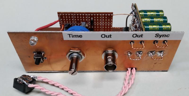
You can get an idea of the size from the pot shaft and BNC connector, and it's 120mm wide and under 45mm high. The baseplate is ~60mm deep, and there are no plans to add a complete case. The test inductor was taken from a Class-D amp board that under-performs rather spectacularly, even after the the PCB errors were fixed. The inductor shown saturates at about 6.5A, far too low for an amplifier that can use a 30V supply and drive 4Ω. The minimum acceptable saturation would be at least 10A, as provided on most other (decent) Class-D amps/ modules.
Without a saturation tester you would never know why the amp had high distortion, even though it uses a competent stereo BTL Class-D amplifier IC. For best fidelity the output inductor shouldn't even come close to saturation, and this example is clearly under-specified. There is no easy way to measure saturation without a dedicated tester. The most expensive part of mine is the 10-turn pot, but I had one that was surplus to other requirements. You can buy them for less than AU$5.00 on eBay (from China), but they are quite expensive from the major distributors (typically AU$30.00 or more).
I ran multiple tests over a period of a couple of minutes, and nothing was even slightly warm, except the test inductor. In short, it does exactly what I wanted it to do, and may end up getting more use than I originally thought it would. It's not handsome, but it is practical and was fairly easy to put together. The following is a more 'advanced' capture, using the scope's cursors to measure the time (Δt) and current (ΔI) before saturation begins.
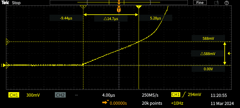
The current is 100mV/A due to the 100mΩ shunt resistor, so 588mV means 5.88A. Using the formula shown above, we can fill in the blanks to get the following ...
L = V × Δt / ΔI
L = 12 × 14.7μ / 5.88 = 30.0μH
My LCR meter says that the inductor is about 31μH, and its printed value says 330 (33μH - it's the one seen in Fig. 3.4). Overall, the correlation is more than satisfactory for checking the value under load and verifying the saturation current. You can see the onset of saturation just beyond the upper right cursors. Saturation is comparatively gentle because the core has an air-gap, but it's still easily seen on the trace. The vertical sensitivity is set for 300mV/division to get a full waveform on the scope. As before, the scope image has been reduced in size to remove the bottom half, as that has no useful information.
The scope was triggered on the displayed waveform rather than the sync output because I used the cursors. Using the sync pulse lets you line up the start with a graticule division, and that makes it easier to take a measurement without the cursors. I re-triggered the tester several times to ensure that the capture was the same each time, ensuring that the measurement is as accurate as possible. Even with multiple captures, the waveform was identical every time, so I know it's as accurate as the scope can measure.
This is far from the 'last word' for inductance saturation testing. I've aimed for a very simple circuit that shouldn't cost too much (or cause too much angst) to build. Although a PIC or other microcontroller could have been used, that would require programming, and there's no point. Allowing a tester to analyse and display results for you might be nice in a production environment if you get your inductors from the local flea market, but that's rather unlikely. Using a scope lets you look at the waveform so you see not just saturation, but its nature (hard, soft, etc.). With experience you'll probably be able to see if an inductor has an air-gap (the saturation curve will likely have a 'break point'), and determine the inductance using the formula shown earlier.
Since we are dealing with the worst passive electronic component of them all, extreme accuracy is not required. We know that the inductance will change with temperature, as will the coil resistance, but at least you'll be able to see some of these flaws in action if you use a heat-gun. Overall, the accuracy is quite good, and the inductor is tested with a load so any anomalies can be seen that won't show up with an LCR meter. It's a given that this project will have limited appeal, but if nothing else it may give you ideas that you can use elsewhere.
With the proliferation of SMPS for just about everything now, if you intend to play with these circuits you need to be able to characterise the inductors - especially if you wind them yourself or 'reclaim' them from other equipment. If a coil runs into saturation in an SMPS, the switching MOSFET may be damaged and the coil will run hot. Efficiency is also dramatically reduced. By being able to measure inductor saturation current you can verify that they will perform as expected, and you can measure the inductance under full load, something that an LCR meter cannot do.
The tester (any version) can also be used with air-cored inductors as used in loudspeaker crossover networks. Unless they have a laminated core they won't saturate, but the tester lets you check to ensure that there is no saturation with iron-cored inductors at the maximum peak audio current they will be subjected to. These are common in commercial speaker crossovers because they are smaller, cheaper, and have lower resistance because fewer turns are required for a given inductance. Evaluation of iron (or ferrite) cored crossover coils is otherwise quite hard to do. This also applies to inductors used in the filter of Class-D amplifiers. Some of the cheap boards you can buy (from China) have inductors that can't handle the peak audio current without saturation. This lets switching noise get through and creates distortion. These can be tested using this circuit.
The filter coil in a Class-D amp using ±50V supplies must be able to pass at least 12.5A without saturating, as that's the peak current into a 4Ω load. If it saturates at a lower current the output will become very noisy and the audio will be distorted across the audio frequency range. Depending on the core material you may measure distortion even if the current is well below saturation. This is a lot harder to test and is probably outside the capabilities of this tester, but you will see more with this tester than with other methods for measuring inductors.
The circuitry is fairly generic, and it uses basic principles. Consequently there are no references to other circuits you will find on-line, and the majority are more complex, with many designed to use an internal oscillator for repetitive pulses so the output can be viewed on an analogue scope. I contemplated this approach, but decided against it. If that's what you need I suggest that you do a Web search to find a suitable candidate.
Measuring Power Inductors - Elektor Magazine (may not be accessible without membership)
Magnetic Properties of Ferromagnetic Materials - HyperPhysics
Ferrite Catalog - Mag-Inc
Ferrite Summary - TDK
How To Avoid Inductor Saturation In Your Power Supply Design - Monolithic Power
Fig. 3.3 is based on a CMOS circuit that appears on numerous sites on-line. It's origin is unknown, but it's a standard CMOS circuit technique.
 Main Index Main Index
 Projects Index Projects Index
|