
|
|
| Elliott Sound Products | Project 25 |
This is a collection of phono (black vinyl for the youngsters) preamps and equalisation circuits, one of which is sure to meet your requirements. These are not my circuits, but were contributed by a reader (see copyright notice below), so I am not really in a position to make any specific recommendations. They are provided as a service to the experimenters out there, and may be found useful for other applications as well.
A quick comment about vinyl equalisation is in order. Although the RIAA and the less used IEC equalisation curves are very precise, it is often thought that the playback system should be as accurate as possible. However, strict adherence to the published response isn't actually very useful, because it was (is) common for the mastering engineer to apply equalisation as the master is cut on the lathe. The reasons can be as simple as trying to actually fit the required number of tracks onto the disc (lots of bass energy takes up a lot of groove space), or the engineer may simply not like the overall balance.
It is still preferable to get an accuracy of better than 1dB across the region from 100Hz up to around 10kHz, but the extremes are often anyone's guess as to what was transferred from tape to the disc. Matching between channels is far more important than absolute accuracy IMO.
While the preamps shown here are all 'interesting', somewhat predictably I recommend Project 06. There have been so many of these built that there are a lot of reviews on-line, and it's also my design (originally designed in around 1980) so it has a long history of very favourable impressions world-wide. There's also a PCB available which makes assembly a great deal easier and less prone to wiring errors. High-performance opamps give excellent results.
The first set of offerings are moving coil preamps, specifically intended for the very low output voltage and impedance of the majority of moving coil pickups. These were much favoured in their day for superior quality over the entire audio range, and for any serious listening many people will still use a moving coil pickup. The 'traditional' way to boost their output level was to use a transformer. These are still available and provide excellent results, but are seriously expensive.
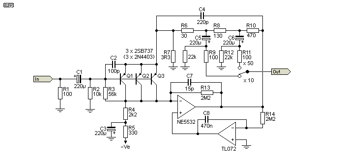
This design uses multiple transistors as the initial amplifying stage. The transistors chosen have very low noise, and this is reduced even further by the parallel technique. The original recommendation was to use 2SB737 transistors, but these may be difficult to obtain. 2N4403 devices should work very well, and they have been used in many very low noise circuits. The transistors should be matched for best performance.
As can be seen from the diagram, the circuit gain can be changed to suit high and low output cartridges with a single switch. The gains as shown are x10 and x50 (20 dB and 34 dB respectively), but could be modified if desired. I leave this up to the reader to experiment with as required.
With the values shown, the circuit has a gain of 192 (set by the feedback resistors in series and the 3.3 Ohm emitter resistor), and this is then attenuated to provide the gains of 50 and 10 as shown. There was an excellent reason for this arrangement, and a reader had the original article and was able to provide it as a reference. The gain structure was set up that way to keep circuit impedances very low. Unfortunately, this would normally load the opamp excessively, but the higher than normal gain prevents excessive loading, and the attenuation brings the level back to sensible values.
Because the input signal is so small, the extra gain is unlikely to cause clipping unless your moving coil has an extraordinarily high output level. The very nature of low impedance moving coil pickups means that high output levels are very unlikely. A 1mV RMS input results in a 192mV RMS output, which will never cause any part of the circuit to clip.
The second opamp (TL072) acts as a DC servo, and ensures that the output of the NE5532 is close to zero. With this arrangement, output offset voltage can be expected to be very low - typically no more than a couple of millivolts. The TL072 has a very low DC offset, but the NE5532 doesn't - the latter is optimised for its AC characteristics, and its DC offset is usually somewhat higher than many other opamps. However, the TL072 DC servo cannot be omitted, because it's needed to correct the large offset created by the input transistors (at least -3V). Note that when power is applied, there will be a high level output 'transient'. A muting circuit should be used to short the output for at least 10 seconds after power is applied.
Note that in common with all DC servo systems, the gain is increased at very low frequencies. There is an extra 6.5dB of gain at 0.7Hz, so a very good rumble/ infrasonic filter should be used to prevent excessive woofer cone excursions and/or feedback. I suggest that Project 99 is a suitable circuit. The low frequency gain can be limited by using a larger cap for the DC servo (increase from the 470nF cap (C8) shown), but this will also result in a longer settling time.
This next design is based on the work of John Linsley-Hood, and again can be expected to give good results. As can be seen, there are no opamps used, and the circuit is 'symmetrical' ¹. This offers a reduction in noise over a single circuit, since the two complete mirror image halves are in parallel so noise is reduced in the same way as the paralleled transistors shown above. Distortion may be reduced as well, but at the signal levels produced by a moving coil pickup, this is not likely to be significant.
- 'Symmetrical' is in quotes because it's really only symmetrical in appearance. NPN and PNP transistors are sufficiently different from each other to ensure that symmetry doesn't actually exist in the real world. However, the upper and lower sections are effectively in parallel, even though this may not be immediately apparent, so noise is reduced in the same way as for MC Preamp #1.
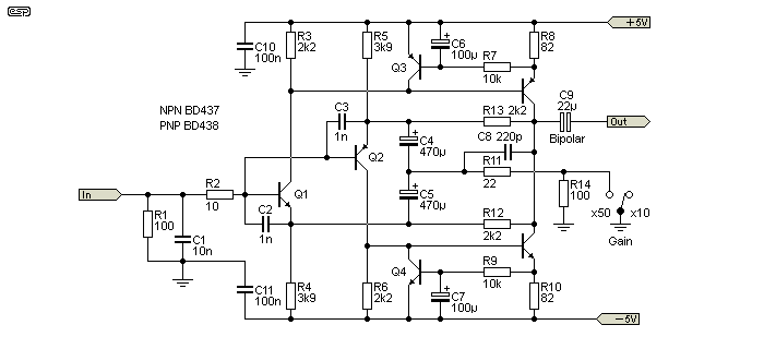
The circuit is (more or less) conventional, using a common emitter stage modulating a constant-current source. As the circuit is mirrored, the current variations are reproduced for both positive and negative supplies. The net output voltage will again have a low DC offset, but probably somewhat higher than the previous design due to the lack of a bias servo to maintain an exact 0V DC output.
Gain is set by the 2.2k resistors from the collectors of the output devices (in parallel, so 1.1k) and the 22 Ohm resistor (Gain=50 position), optionally in series with the 100 Ohm to give a gain of 10. This circuit originally had an ill advised moving magnet cartridge option, but I would not recommend this circuit be used at all with a moving magnet pickup cartridge, even if the 100 ohm input resistor is removed.
The theoretical gain is 50 (34dB) in the 'Gain = 50' position, or 10 (20dB) for the 'Gain = 10' setting. In practice, one can expect the gain to be very slightly less than these figures, especially for a gain of 50.
I cannot comment on the relative noise performance of these two preamps, but as they are both based on designs by well respected audio designers, I would expect that noise would not be an issue with either circuit.
NOTE: The general circuit topology shown in Figure 2 was first published in Sweden in 1975 (The magazine was Radio & Television), written by Peter Akemark (AKA Per Elving). This predates the JLH article by about 8 years, as the version shown above was published in 1983).
There are quite a few moving coil 'head amp' circuits on the Net, but some are wildly over-complicated and others are simple, but suffer from a variety of problems. One that looks attractive at first is a design by J. Marshall Leach, which uses a pair of transistors operated in common base mode. The input goes to the emitters of the two input devices, and the supply is a 9V battery. Unfortunately, the gain of the circuit depends greatly on the battery voltage, source impedance and load impedance so it's not a design that can be recommended. This is a pity, because the circuit is very simple and probably works quite well, but if the gain changes as the battery discharges this makes the circuit useless. Obtaining accurate channel matching is likely to be a great challenge, and each channel needs its own battery.
There are several other head amps that can't be recommended, so those shown here are the only ones I intend to publish and describe in any detail.
With three different circuits and several additional EQ networks to choose from (plus my own version, published as Project 06), there has to be one for you! One thing that most phono preamps use is a feedback network to provide the RIAA equalisation. That this works is not questioned, but the vast majority have one significant error term, in that high frequency rolloff does not extend much past 20kHz. The minimum gain of a non-inverting feedback derived EQ network is unity, so at some frequency (above 20kHz) the response flattens out, rather than continuing to roll off to well beyond 50kHz or so.
There has been an attempt to cure this in Preamp #1 (with R9 and C8), and it doesn't exist in Preamps #2 or #3. Project 06 (ESP's phono preamp) does not have this issue, but the majority that you'll see elsewhere do, and most have no network to ensure the rolloff continues much beyond 25kHz or so. In general, I suggest that you avoid any phono preamp that cannot maintain the HF rolloff to at least 100kHz, and preferably much higher.
I do not know the origin of these circuits (other than from Richard), so cannot be too specific about them. They are both reasonably conventional, as can be seen. Note that these circuits all show a 220pF cap (shown greyed out) across the 47k input loading resistor, and with the vast majority of cartridges this is a bad idea and it should be omitted. For information on cartridge loading, see the article Phono Cartridge Loading. Most cartridges need the lowest possible capacitance to prevent high frequency peaking and/or premature rolloff.
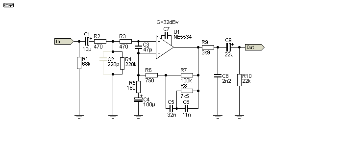
This is a simple, one opamp phono preamp, but has a few added features. These are mainly for radio frequency (RF) suppression, and with the input circuit shown can be expected to be highly resistant to even high levels of RF interference.
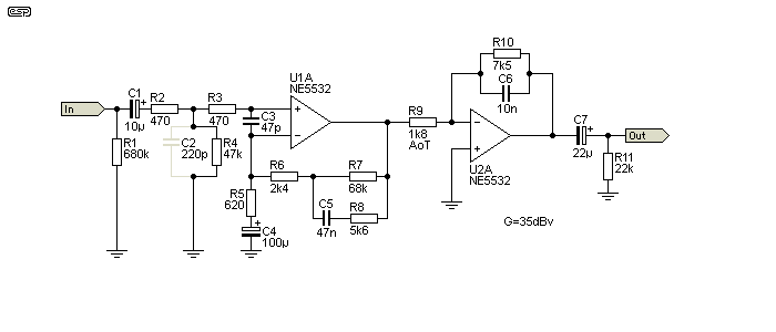
This preamp splits the equalisation into two stages - the first stage provides the low frequency boost required by the RIAA specification, and the second reduces the high frequency component (again, to the RIAA spec.). The advantage of this approach is that the two filter sections have less interaction, and much of the circuit noise produced by the first (and second) stage is attenuated by the top-cut circuit.

As can be seen, this preamp is considerably more complicated than the first two, but includes a 3rd order rumble filter with a cutoff frequency of about 18 Hz.
The first stage is a simple amplifier, again with complete RF interference protection. This is followed by the rumble (infra-sonic) filter, and finally the equalisation stage. Note that in this circuit arrangement, the opamp is operating as an inverting amplifier, which has no bearing on the final result, but is (very) slightly noisier than the non-inverting configuration. This is unlikely to be audible in practice, since the gain contributed by the final stage is much lower than normal.
Total gain is 39 dB, of which 17.5 dB is contributed by the input stage, 6 dB by the filter, leaving only 15.5 dB gain in the final stage. All preceding high frequency opamp noise is attenuated by the RIAA equalisation, leading to a design which should have an excellent overall noise figure.
These EQ networks can be used around any opamp, and will provide RIAA equalisation to an accuracy as shown next to each diagram. Some care must be used to ensure that the feedback resistor (to ground) is selected to give the required gain. Unless these networks are included in an inverting opamp stage, rolloff beyond 25kHz or thereabouts cannot be maintained. In a 'conventional' single stage non-inverting topology, an additional network must be added to maintain the rolloff of high frequencies to beyond 100kHz. This is not shown as it depends on the circuit gain and RIAA network characteristics.
The gain is specified at 1 kHz for all phono preamps, because of the frequency characteristics of the filter network.
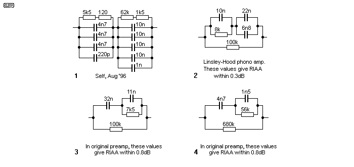
The 1 kHz impedance of each network is quite different, so the required feedback resistor has been calculated for a nominal gain of 35 dB (x 56) . These work out to (approximately) ...
| Circuit Nr. | Network Z | Feedback Res. | Actual Gain |
| 1 | 7.75 k Ohms | 138 Ohms | 56.6dB |
| 2 | 10 k Ohms | 180 Ohms | 57.0dB |
| 3 | 9.43 k Ohms | 168 Ohms | 56.6dB |
| 4 | 67 k Ohms | 1.2 k Ohms | 56.8dB |
With this in mind, the 1 kHz gain resistor can be calculated. For example, using (1) above, for a gain of 35dB (a gain of 56 for ease of calculation), this will need a resistor to ground from the -ve input of the opamp of 138 Ohms.
For the sake of reference, the table below shows the response curves for both RIAA equalisation, and the IEC modified version. The latter was not very popular, because it represented a loss of bass (-3 dB ref RIAA at 20 Hz). For anyone wanting to know a little more about how and why the equalisation was done in this way, read on ...
| Hz | RIAA | IEC | Hz | RIAA | IEC | Hz | RIAA | IEC | ||
| 20 | 19.36 | 16.35 | 240 | 7.04 | 7.01 | 2400 | -3.39 | -3.39 | ||
| 22 | 19.24 | 16.62 | 270 | 6.25 | 6.23 | 2700 | -4.04 | -4.04 | ||
| 25 | 19.04 | 16.89 | 300 | 5.57 | 5.55 | 3000 | -4.65 | -4.65 | ||
| 28 | 18.83 | 17.04 | 340 | 4.80 | 4.79 | 3400 | -5.43 | -5.43 | ||
| 31 | 18.61 | 17.09 | 380 | 4.16 | 4.15 | 3800 | -6.17 | -6.17 | ||
| 35 | 18.29 | 17.06 | 430 | 3.49 | 3.48 | 4300 | -7.02 | -7.02 | ||
| 39 | 17.96 | 16.95 | 480 | 2.93 | 2.92 | 4800 | -7.82 | -7.82 | ||
| 44 | 17.54 | 16.73 | 540 | 2.38 | 2.38 | 5400 | -8.70 | -8.70 | ||
| 49 | 17.12 | 16.45 | 610 | 1.86 | 1.86 | 6100 | -9.64 | -9.64 | ||
| 55 | 16.61 | 16.07 | 680 | 1.43 | 1.43 | 6800 | -10.50 | -10.50 | ||
| 62 | 16.02 | 15.59 | 760 | 1.02 | 1.02 | 7600 | -11.39 | -11.39 | ||
| 70 | 15.37 | 15.03 | 850 | 0.63 | 0.63 | 8500 | -12.30 | -12.30 | ||
| 79 | 14.67 | 14.40 | 950 | 0.26 | 0.26 | 9500 | -13.22 | -13.22 | ||
| 89 | 13.93 | 13.72 | 1100 | -0.23 | -0.23 | 11000 | -14.44 | -14.44 | ||
| 100 | 13.18 | 13.01 | 1200 | -0.52 | -0.52 | 12000 | -15.17 | -15.17 | ||
| 110 | 12.54 | 12.39 | 1300 | -0.79 | -0.79 | 13000 | -15.85 | -15.85 | ||
| 120 | 11.94 | 11.82 | 1500 | -1.31 | -1.31 | 15000 | -17.07 | -17.07 | ||
| 130 | 11.38 | 11.27 | 1700 | -1.80 | -1.80 | 17000 | -18.14 | -18.14 | ||
| 150 | 10.36 | 10.28 | 1900 | -2.27 | -2.27 | 19000 | -19.09 | -19.09 | ||
| 170 | 9.46 | 9.40 | 2100 | -2.73 | -2.73 | 21000 | -19.95 | -19.95 | ||
| 190 | 8.67 | 8.62 | ||||||||
| 210 | 7.97 | 7.93 | Reference | 1000 | 0 | 0 | ||||
Sometimes you will see the RIAA (or IEC) response described as a time constant rather than frequency turnover points. The two are directly related, and the time constants are determined by 1/(2π f). Frequency is 1/(2π t) (where 't' is time constant), and for the RIAA equalisation curves, these are ...
The basic principle behind the equalisation curve was quite simple, and was designed to reduce the grove modulation to a manageable level (both for the cutter and the reproducer), and provide some basic high frequency noise reduction.
With this in mind, frequencies below 500 Hz were cut (on the cutting lathe) using constant amplitude, which means that the signal from the cartridge will increase at 6 dB/ Octave, since if the amplitude remains constant, the velocity must increase with the frequency. Because the output of a magnetic cartridge is dependent upon the velocity, bass boost must be applied to bring the levels back to normal.
It is this rather large amount of bass boost that accentuates the mechanical noise of a turntable, producing what is commonly known as rumble. There is also the risk of low frequency feedback if the turntable is not capable of isolating the platter and tone-arm from the listening room environment. Timber floors and rigid suspension increase the risk of feedback, and many manufacturers went to extreme lengths to provide isolation and very low levels of low frequency noise.
Above 500Hz, the cutter mode changed to constant velocity, so the output of the cartridge will now be independent of frequency. Vinyl (or any other material for that matter) will collect dust, and will also have minor surface imperfections, so all signals above 2100 Hz are boosted (again at 6 dB / Octave), so the playback equalisation curve now applies treble cut. This brings the signal level back where it should be, and reduces disc surface noise as well.
It's worth pointing out that some people may go to extreme lengths to obtain exact RIAA equalisation, but in reality this is not necessary. When vinyl disc masters were cut, it was not at all uncommon for the engineer to apply some EQ to make the end result sound "right" (to him, with his monitors) or to ensure that no signals were cut that would compromise the pressings (excess bass, extreme transients, etc.). As a result, the listener has no idea what the original master tape sounded like, and small deviations will usually be within the expected response of even the best loudspeakers.
In general, it's not unreasonable to expect that equalisation should be within 1dB, but attempting to obtain substantially better than this is usually not warranted. EQ accuracy of 0.1dB might look good, but your speakers and room won't even come close to that, so the extra accuracy is wasted. Naturally, if a component combination happens to provide very good accuracy, then no-one is likely to be offended by the end result.
What is extremely important is channel matching. Measuring the caps (and even the resistors) to obtain the best possible match for all gain and equalisation components preserves the stereo image and is far more critical than a small variation in the RIAA equalisation curve. You can be assured that cutting lathes have very well matched EQ stages for just this reason.
I also strongly recommend that anyone looking at phono preamps have a look the ESP article Phono Cartridge Loading. As noted above, any preamp with a capacitor across the input is a bad idea, and 220pF is almost always too much. Increased capacitance will most likely cause a response peak within the audio band, and will also adversely affect the extreme high frequency performance.
 Main Index
Projects Index Main Index
Projects Index
|