
|
|
| Elliott Sound Products | Project 247 |
 Main Index
Projects Index Main Index
Projects Index
|

I have had several enquiries from people looking for tape head preamps. There has been something of a resurgence in tape lately, and a suitable preamp can be mode using the Project 06 phono preamp board. Unfortunately, there are several different standards in common use. This means that you either have to use switched capacitors and resistors, or have separate preamps for each standard you intend to use. NAB (National Association of Broadcasters - US) and IEC (International Electrotechnical Commission - RoW). Naturally, they are different.
Note that this preamp is specifically intended for reel-to-reel (aka RTR) machines, using a tape speed of 7½ ips or 15 ips (inches/ second). It's not suitable for compact cassette decks, and adding a high-quality preamp to those is rather pointless anyway, because they are not high-fidelity. Some are pretty good, but even the best is sub-par compared to quality vinyl or CD.
One of the reasons I've avoided attempting a tape-head preamp is that I have no way to test it. That means I have to design based on the EQ curves, and analyse (the few) circuits that appear to be designed properly. While it's not hard to duplicate the EQ curve(s) closely, they never consider the response of the tape head (which forms a part of the equalisation). This isn't helped by circuitry that was used when tape was in its heyday is no longer relevant to modern design. My philosophy has always been to verify that every circuit published will perform as expected, but for a tape-head preamp I have to abandon that. To say it makes me uncomfortable is serious understatement!
Please Note: Since this project was published, I have had a number of enquiries regarding specific designs for different machines. I cannot (and will not) attempt any such design, as it would require that a) I have a machine with heads identical to those you have, and b) that I have tapes (including alignment tapes) that I can use to verify the design. I have neither, and I have no interest in acquiring same. I don't have or use a reel-to-reel machine, and as noted below the head forms part of the EQ network. Please don't ask for any design work - I won't do it because I cannot test and verify the results.
Some service manuals show that EQ was at best an approximation, with little or no attempt to make it accurate. Provided a tape could be recorded and played back sounding much the same as the original, that was 'good enough'. Professional machines often use fully adjustable EQ, so the machine could be aligned to reproduce a standard tape within acceptable limits. For anyone without a reference tape this is clearly impossible. There are many interdependencies with tape machines, and I can only provide a basic EQ scheme.
NAB isn't too difficult, because the same EQ is used for both 7.5 and 15 ips (inches/ second), or 190.5 and 381mm/s (more commonly quoted as 19 and 38 cm/s). IEC is different from NAB at both speeds, and the two speed EQs are also different from each other. It's common to quote EQ of this type in microseconds, referring to the resistor/ capacitor time constant. Unfortunately, a tape that was recorded using one standard will be very wrong if played back using the other. The time constants are shown below, for the most likely NAB and IEC requirements.
| Tape Speed | CCIR/ IEC1 | NAB/ IEC2 | ||
| Bass Pole | HF Zero | Bass Pole | HF Zero | |
| 15 | None | 35μs | 3,180μs | 50μs |
| 7½ | None | 70μs | 3,180μs | 50μs |
For any time constant, simply multiply by 2π and take the reciprocal. The formula is simply 1 / ( 2π ×TC ). A time constant of 3,180μs is a frequency of 50Hz. A pole in the response causes the signal to roll off at 6dB/ octave beyond the pole, and a zero causes the response to flatten out again. The signal level can usually be taken to be ≤1mV at 1kHz, so quiet opamps are essential.
Because we have a bass pole at 50Hz for NAB, a tape recorded using IEC EQ but played back using NAB will sound bass-heavy by about 8dB (20Hz). The high-frequency response will also be wrong if the matching playback EQ isn't used. The three high-frequency poles are at 4.55kHz (35μs), 3.18kHz (50μs) and 2.27kHz (70μs). These (mostly) can't be made using standard values, so I suggest using parallel capacitors to get the frequencies needed.
The time constants described here suit 'modern' standards only. Any tapes recorded before ca. 1968 may have used older EQ settings that were different from those adopted in later machines. In a few cases it may not be possible to determine the standard that was used (a couple of proprietary 'standards' have also been listed [ 1 ]). In such cases, your only option is to equalise 'by ear', adjusting a suitable EQ system until the recording sounds balanced. It's not scientific, but a reasonably skilled person should be able to get very close. If the equalisation resistors shown in the following circuits are made adjustable (i.e. pots), almost any EQ that follows the general scheme can be achieved. A selection of switched capacitors can also be added for greater flexibility.
NAB equalisation is shown below, and the same curve is used for both 7½ ips and 15 ips. IEC equalisation doesn't include the bass shelf, where the response levels out below 50Hz. IEC continues to boost the bass down to around 10Hz. This means there's about 8dB more bass at 20Hz. IEC also uses different time-constants for 7½ ips and 15 ips. This means that if you have both NAB and IEC tapes at 7½ ips and 15 ips, you need three different EQ curves.
Professional tape machines all used adjustable EQ for both record and playback, so the EQ could be tweaked to get the response to agree with a standard test tape. The idea was to adjust the playback using the test tape, then adjust the record EQ so that playback was flat. After this, the machine was set up to be standard for both record and playback, so tapes could be interchanged with other machines and have the same frequency response. The adjustment allowed for tape head and all electronics to be fully compensated. I don't propose to provide a fully adjustable EQ system.
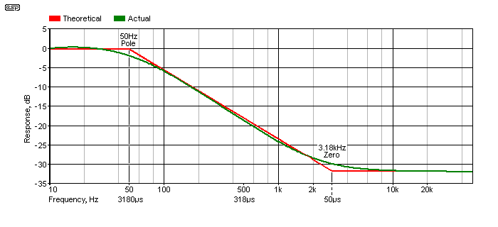
Figure 1 - NAB Equalisation - Theoretical And (Idealised) Actual
The above graph shows the theoretical and (idealised) actual response of a NAB EQ stage. The two time constants are 3,180μs (50Hz) and 50μs (3.18kHz), and the actual curve follows the general trend of the ideal, but cannot follow it exactly because the laws of physics get in the way. All machines will have a curve similar to the 'actual' curve shown. The final 100Ω and 10nF network (see Fig. 2) attenuates anything over 160kHz. You can increase the value of R8(L/R) if you wish - 220Ω gives a -3dB frequency of 72kHz. I wouldn't exceed 330Ω though (-3dB at 48kHz). C4(L/R) can be omitted if you prefer.
The terms 'pole' and 'zero' need some (in this case simplistic) explanation. A single pole causes the signal to roll off at 6dB/ octave (20dB/ decade), and a single zero causes boost at the same rate. If a zero is introduced after a pole (as shown above), the effect is to stop the rolloff - back to flat response. The flat response is seen from 3,180Hz up to the maximum (20kHz).
As noted further below and elsewhere on the ESP website, striving for 'perfect' accuracy is pointless, as so much depends on the recorded material. No-one knows how the tone controls were set when the tape was recorded. When you purchase (or acquire by whatever means) a tape, no-one tells you what EQ was applied during the mastering process, the high frequency response degrades after the tape has been played many times, so ultimately you have to let your ears be the final judge of what sounds right to you.
Consider using (preferably tailored response) tone controls to allow the adjustment of the final EQ so it sounds 'right'. This is subjective of course, but any system has to sound right for the person listening to it. It's rather pointless having a system that's allegedly 'perfect', but doesn't sound any good to the owner. Accuracy is a much-touted benefit, but there are so many other influences that can make an ideal system sound wrong (listening room, age of listener, etc., etc.). Changing equipment is a very expensive replacement for a decent tone control circuit.
For a 'typical' tape head (if such a thing exists) you need around 50dB of gain at 1kHz. Some heads have lower output than others, and will need more gain to get a usable output level. Others may provide more output, and therefore require less amplification. The circuit shown next has 50dB of gain at 1kHz. It's suitable for use with tape heads that output around 1mV (1kHz)
Like most other ESP projects, it is very tolerant of opamps but the LM4562 is suggested, or the NE5532 can also be used. The LM4562 is a very low noise, high speed device with excellent characteristics, and is a reasonable price. It is ideally suited to this sort of application. Another you might want to try is the OPA1642 - it's a little noisier (5.1nV√Hz) but has JFET inputs that some people may prefer. It's only available as SMD.
Note that if a very low output tape head is used, a step-up transformer may be required before the preamp. Some tape machines used this approach, but mostly for very early models. After low-noise transistors became available this requirement (mostly) went away. However, most tape heads have a fairly low output level. Don't expect more than 1mV at 1kHz. To keep resistor thermal noise to a minimum, I've used a low-impedance feedback network. It can be scaled for higher resistance (and lower capacitance), but at the expense of higher noise.
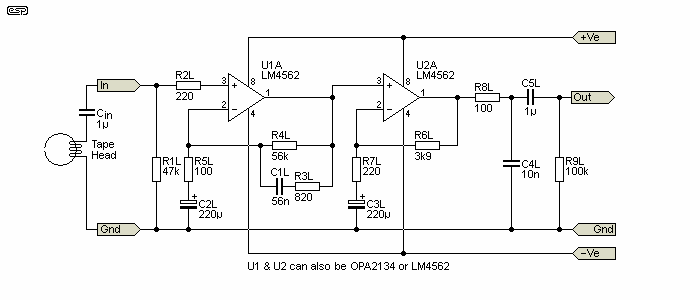
Figure 2 - Tape Preamplifier, NAB Equalisation Shown
For IEC, C1 needs to be 43nF for a 35μs time constant (15 ips) or 85nF for 70μs (7½ ips). R4 has to be increased to 270k. It's easier to leave R4 connected permanently, and for NAB a 68k resistor is switched in parallel. The values for C1 are decidedly non-standard, but 43nF is made with 39nF || 3.9nF. 85nF is 68nF || 18nF. (|| means in parallel.) The values aren't exact, but are well within an acceptable tolerance.
Note: The 1μF cap (Cin) at the input is external (not on the PCB). It must not be omitted, because any input offset from the first opamp will put DC through the tape head, magnetising it. This leaves your tapes with residual unidirectional magnetisation, which increases noise that cannot be removed (i.e. the tape may be ruined!). Do not omit this capacitor!
With the values shown, the circuit has a nominal gain of 50dB (actually 48dB or ×250) at 1kHz, allowing for a 1mV output from the replay head for an output level of around 250mV. This may not be enough - it depends on the sensitivity of your tape head and preamp. The gain can be increased by increasing the value of R6. If it's made 10k, the gain of the second stage is 33dB (x46), giving an output level of about 650mV (1mV input at 1kHz). This provides a total gain of 60dB at 1kHz.
Few people have the ability to measure the inductance of the playback head, capacitance of their interconnects or the internal playback head cables, but all will have an effect on the overall equalisation. This is just one reason that professional machines provide calibration adjustments. In some cases there will be a capacitor in parallel with the playback head, but this is machine dependent and without a standard playback tape you shouldn't attempt to mess with the EQ.
The high value capacitors could be non-polarised electrolytic types, since they will have (virtually) no DC voltage across them. However, these are quite large, and standard (polarised) electrolytics may be used instead. Polarised caps will function normally without DC bias, but do not use tantalum caps - they are my least favourite capacitor type, and are not recommended for use with zero DC bias. Standard aluminium electrolytics are actually perfectly alright with no bias (despite what you may have read), and if sufficiently large (in value) will contribute virtually no measurable distortion.
The AC voltage across C2L/R and C3L/R will never exceed ~5mV at any frequency down to 10Hz, and these caps play no part in the equalisation process. Feel free to increase the value if you wish (470µF is not a problem if they fit the board). The polarity depends on the opamps you use - provided the DC voltage across the cap is less than 100mV either polarity is fine.
The low value capacitors should be 2.5% tolerance if obtainable, otherwise you may be able to measure a selection of standard tolerance caps to find those which are closest to the required value - preferably to within 1%. Some deviation from the ideal equalisation curves will occur if these caps are too far from the designated values. More important is matching between channels - this should be as accurate as possible.
Only one channel is shown, the other channel uses the remaining half of each opamp, the pinouts of which are shown on the diagram. Remember that the +ve supply connects to pin 8, and the -ve supply to pin 4. The circuit as shown is intended to drive normal preamp inputs with an input impedance of around 22k. If your preamp has a lower input impedance, increase the value of C5 (L+R). Up to 10μF is appropriate, either a non-polarised electro or a standard polarised electro can be used.
Opamps are bypassed from each supply line to ground with a 10μF electrolytic and a 100nF polyester or ceramic capacitor to ensure stability. These parts are all provided for on the PCB.
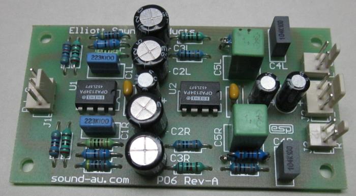
Photo of Completed Unit (P06 Components Shown)
The photograph above shows a complete preamp using the PCB. This is actually a P06 phono equaliser, but the only things that change are a few values, with some parts off-board if you use switchable EQ. It's the Revision A version of the board. The latest version is Revision B, but the differences are academic. If you need switchable EQ, there's a bit more work involved, with C1L/R and R3L/R being mounted off-board to allow for switching. Remember to include the external input capacitor.
To be really useful, it's necessary to include switching for NAB or IEC. The latter requires two time-constants, because the EQ changes with tape speed. I only intend to show the EQ for 7½ and 15 ips, as lower tape speeds cannot provide acceptable fidelity. It may be alright for casual listening, and the internal EQ will almost certainly be quite acceptable for the lower speeds (3¾ ips [4.5 cm/s] and below is comparatively low fidelity).

Figure 3 - Switched NAB + IEC Equalisation
For NAB, C1x (external) is 56nF with R1x (68k) in parallel. For IEC, R1x is removed from circuit, C2x 43nF for 15 ips and C3x is 85nF for 7½ ips. As noted above, The values for C1 are not standard, so 43nF is made with 39nF || 3.9nF. 85nF is 68nF || 18nF (|| means 'in parallel'). The response of each configuration is shown next. The level is arbitrary, and it can be varied by changing R6(L/R). A higher resistance means more gain.

Figure 4 - NAB And IEC Equalisation Curves (Default Gain)
Note that I have only shown the values and time constants for 15 ips and 7½ ips. For serious listening, anything slower is a serious compromise, and cannot be recommended. Before construction, I strongly recommend that the intrepid constructor consider that the EQ circuits inside the machine are probably quite accurate, and capable of performance commensurate with the quality of the tape deck. A cheap deck will also have cheap heads and may not have acceptable tape speed accuracy for 'quality' listening.
If you do have an alignment tape, it's possible to make R3(L/R) and R1x variable over a range of perhaps 0.75 to 1.5 times the nominal resistance. This lets you adjust the turnover frequencies to get the playback response as flat as possible. This is the technique used in many professional machines. Adjusting R3 (in particular) will change the mid-frequency gain, but that's unlikely to be a major issue. It may also be necessary to alter the gain of the second stage to get the output level you need. R6(L/R) can be increased as needed
As noted in the introduction, this is one of very few circuits on my site that I cannot test. The curves are acceptably accurate (based on the 'standard' time-constants), but the response of the replay head cannot be included or estimated. Different machines will use heads with a different 'native' response, and the output level is indeterminate. Based on the information I could find, around 1mV at 1kHz is probably 'typical', but that can be expected to vary by ±6dB in reality (500μV to 2mV). However, some heads may have much lower output (~250μV), and there's no way that this can be verified without having a reel-to-reel tape deck (which I don't).
Without a reference tape (used for alignment), there's no way that the final EQ can be verified, so even if you build the preamp, you likely won't really know if it's any better than the one you already have. In some cases people may want to build a preamp simply because they can. I don't have a problem with that approach, and if anyone does so and has information that I can include here, feel free to contact me and let me know.
The design must be considered experimental, because of the many variables and my inability to run tests because I don't have a tape deck. The responses have been calculated and simulated, and there's no doubt that the circuit will work. The doubt is whether it will be any better than the circuitry you already have in your tape machine. Using an LM4562 opamp should provide a noise level that's at least as good as the best of the semi-professional decks, but some employed the highest quality circuitry available at the time, and would be very good.
All-in-all, there are too many unknown factors involved in a tape head preamp for general use, and this is why I never published a circuit until now. Should you decide to build it, be aware that I can make no representations as to its suitability for your tape machine. It might be 'better' it may be worse or it might even be the same as what you have already. For people who use reel-to-reel tape, it could be an interesting experiment if nothing else.
Of course, all of this relies on the tape transport, head condition and the quality of your tapes. A dodgy transport may have issues with supply and take-up tension, capstan and pinch roller, tape guides and everything else that comprises the deck as a whole. Unless everything is in tip-top condition, you risk damaging possibly irreplaceable tapes. These degrade with time anyway, with oxide-shedding being a serious problem with old tapes. Rather than using a tape deck as a default source, I'd transcribe tapes to digital, encoded as 'WAV' or 'FLAC'. You could also consider 'OGG' (Ogg Vorbis) if lossy compression isn't an issue for you. Given the cost of digital storage media now, a lossless format is preferred, even if you can't resolve the full bandwidth.
The primary reference is Replay Equalisation - iasa (International Association of Sound and Audiovisual Archives
There are no other specific references, other than information gleaned from a number of service manuals. These were for the Revox A77, Nagra 4, plus a couple of Ampex manuals. This was (for the most part) not very helpful. Getting credible information on 'typical' tape head parameters is well nigh impossible - plenty of opinions, but few facts.
| Main Index
Projects Index
|
| Copyright Notice. This article, including but not limited to all text and diagrams, is the intellectual property of Rod Elliott, and is © 2023. Reproduction or re-publication by any means whatsoever, whether electronic, mechanical or electro-mechanical, is strictly prohibited under International Copyright laws. The author (Rod Elliott) grants the reader the right to use this information for personal use only, and further allows that one (1) copy may be made for reference while constructing the project. Commercial use is prohibited without express written authorisation from Rod Elliott. |
