
|
| Elliott Sound Products | Project 241 |
 Main Index Main Index
 Projects Index Projects Index
|
In general, we make most audio measurements using flat response, from just a few Hertz up to the limits of our measurement system. If we're using an oscilloscope, the response extends to at least 20MHz, so a great deal of high frequency noise becomes part of the measurement. Many digital scopes have a filter that can be used, but IMO they are pretty useless, because the frequency resets of you change the timebase. While these can be useful, it involves a lot of messing around.
Wide bandwidth is rarely useful if we're measuring signal to noise, or determining the maximum noise across the audio band. Most semiconductors have '1/f' noise that increases as frequency is reduced. The maximum level is reached at very low frequencies, down to less than 1Hz.
The ITU-R Recommendations constitute a set of international technical standards developed by the Radiocommunication Sector of the ITU (International Telecommunication Union - formerly CCIR) ). These are European standards/ recommendations, and the latter are just that - recommendations. They are not mandatory, but if the appropriate recommendation is used (in this case Z-Weighting) you know that you can compare like with like.
One can always devise a filter that removes high and low frequency noise, but if you're going to do so, it may as well follow the ITU recommendations so that your measurement can be relied upon to be reproducible by others using the same filter criteria.
Z-Weighting is in contrast to A-Weighting, which has been used for many years, often to artificially inflate the signal to noise ratio (SNR). I've never liked the way most people use A-Weighting, and more details are available in the articles A-Weighting and A-Weighting - Is it the metric you think it is?
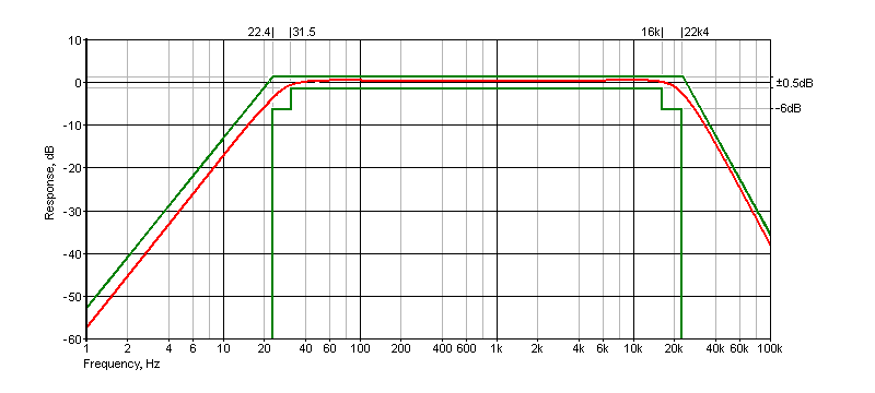
The unweighted, flat frequency response curve is shown below in Fig. 2, with the 'mask' shown in green. The band limiting filter frequency response bounds form the 'mask' in the ITU Recommendation ITU-R BS.468-4 for the Measurement of Audio-frequency Noise Voltage Level in Sound Broadcasting. International Standard IEC61672 defines a similar, flat response over audio frequencies as 'Z-Weighted' or zero weighted. The mask shows the allowed limits, and the filter response must remain within the mask at all frequencies of interest.
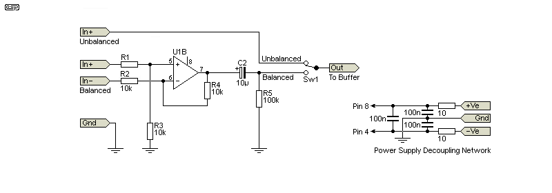
In some cases, you may prefer a balanced input. This uses U1B, and is a completely standard balanced input circuit. The input impedance is nominally 20k, but this can be increased or reduced at your discretion. This circuit has a gain of unity when fed with a balanced input, so recalibration of the filter's 0dB gain is not necessary. The DC supply filter should be used whether you use the balanced input or not.

Sw1 lets you select between balanced and unbalanced inputs. You could just use the +In terminal of the balanced circuit, but you'll be adding noise that may be greater than the circuit being tested. This is unhelpful, so it's better to switch out any circuitry that's not being used. If you don't need the balanced input, disable U1B (Pins 6 & 7 joined, Pin 5 grounded) and the switch is not needed.
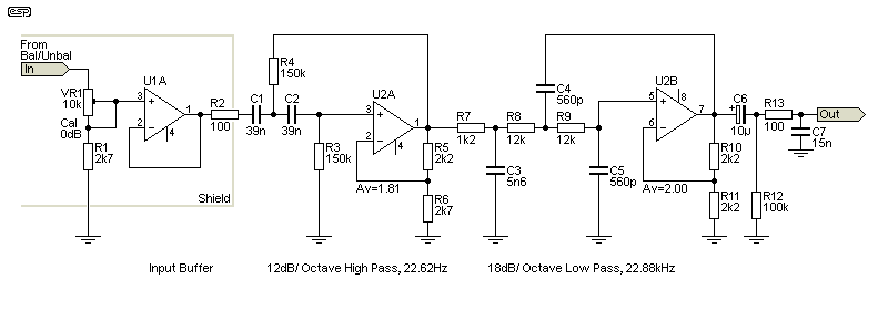
A Z-Weighting filter sets boundaries, with the nominal -3dB frequencies set to 22.4Hz and 22.4kHz. The recommended slopes are 12dB/octave for the high-pass filter (22.4Hz), and 18dB/octave for the low pass (22.4kHz). There are many approaches that can be taken to get the response to fit inside the mask, but Sallen-Key filters are the easiest to implement. Because the Q needs to be tightly controlled, the 'equal-value' filter is the best choice, as this makes component values easier to obtain. The final filter Q is 'tweaked' by adjusting the opamp gain, and both filters are defined as Chebyshev, having a slight rise before rolloff. With the gain I selected, this is +0.4dB at 48.9Hz and +0.1 dB at 19.85kHz, so it remains comfortably within the mask. You may wish to extend the lower limit very slightly, which can be achieved by adding 5.6k resistors in series with the two 150k resistors (R2 and R3). This extends the -3dB frequency by a little over 0.7Hz (21.4Hz vs 22.2Hz, close enough). Personally, I don't think it's worth the extra trouble. Alternatively, use 160k resistors, which move the lower -3dB frequency down by 1.3Hz.
The filter has better performance than anything that can be built (affordably) using inductors, and as long as the input is restricted to ~±10V (7V RMS) it will give a good account of itself, although I recommend that the input should be kept below 5V RMS. To get maximum rejection of a Class-D amp's switching frequency (or other high frequency noise), the input stage must be shielded from the rest of the circuit. The shielding has to be more than a simple screen, and will require that the input opamp's supplies are decoupled, using 100Ω resistors and 100nF multilayer ceramic caps, both with very short capacitor leads. Shielding to this level is almost an artform, so you must be prepared to experiment. You're looking for at least 60dB attenuation at 200kHz.
Although not shown (to simplify the schematics), each opamp must have a 100nF multilayer cap from each supply pin to ground. Pin 8 is positive and Pin 4 is negative for standard dual opamps. The recommended supply voltage is ±15V, and Project 05 is ideal. You can also use Project 05-Mini, but it's not as quiet. The difference in real terms is minimal though, because the PSRR of most opamps is very good.

The circuit is straightforward, and uses only standard E12 resistor values. Capacitors will need to be selected, because they have to be within 1% to get an accurate response. For home use, this isn't essential, because a small error won't cause any problems, and all measurements you take will have the same filter. This will help you to be able to compare audio circuits, and the results will be consistent. Note that the output is intended to drive high impedance loads, such as oscilloscopes or millivolt meters. The minimum suggested load impedance is around 22k, giving a 5mV level drop from a 1V input.
The input shield is designed to prevent high frequency noises on the input signal from radiating through to the rest of the circuit. How it's implemented is up to the constructor, but all openings (for R2 and the supplies) should be only just large enough for the resistor or wires to fit through. If the openings are too large, HF noise will get past the shield, defeating the purpose. Use heatshrink tubing around R2 to ensure that it can't short to the shield. The input impedance will be around 10k when VR1 is adjusted for unity gain. The input is either direct from the 'outside world', or via the balanced/ unbalanced switch shown in Fig. 3. I recommend a BNC connector for the unbalanced connector, but you can use anything that suits your test setup. The same applies to the output connector.
I shall leave the opamp selection to the reader. An NE5532 or perhaps OPA2134 would be a good choice for U1 (balanced input and buffer), and a JFET input opamp is better for the filter. This is because the impedances are higher, and JFET opamps have much lower current noise than bipolar types. The feedback resistors are the lowest practicable values to minimise noise without stressing the opamp outputs. For most general purpose work, TL072 opamps will be good enough for the filters, but you can use sockets and try something 'better' if you prefer.
The low-pass filter is the final circuit (including R13, C7) to minimise high frequency noise. Most of the circuit noise you'll measure is at the higher frequencies, so it makes sense to filter out as much noise from the filter as possible. Both filters operate with gain, so the input attenuator is there to ensure that the output level is within 0.5dB of the input. The gain of the first stage is 1.81 (5.17dB) and the second is 2 (6dB). That's a total gain of 11.19dB, or ×3.628. If the calibration were done at the output, noise would be a little lower, but the input voltage would be limited to a maximum of about 2V RMS. With the attenuator at the input, the circuit can handle up to 5V RMS. There's a 'golden rule' for circuitry that basically says 'thou shall not attenuate before amplification', but sometimes there's no other sensible choice.
In this design, the 560pF caps will typically be NP0/ C0G ceramic (not high 'k' ceramics), with polyester caps used for the higher values. Polypropylene caps can be used if you wish, but I doubt that you'll measure the slightest difference. The response curve is shown in red, with the mask in green. The response fits inside the mask quite well, but if you don't select the capacitors to within 1% that may not be the case. The resistors should all be 1% metal film types.
In theory (and with very careful layout), the low-pass filter is sharp enough to allow (1kHz) distortion measurements with Class-D amplifiers. These are always difficult, because the high-frequency switching waveform is notoriously difficult to remove. Audio Precision has an add-on unit for just this purpose, but it's intended to be able to handle close to the full output level of the amplifier. This is better for distortion measurements because the signal level is higher, but it uses LC filters (inductor-capacitor), as opamps aren't capable of accepting such high amplitudes.

The response within the pass band has an allowance of ±0.5dB. The final filter (Fig. 2, R13, C7) is designed to ensure that very high frequencies (beyond 100kHz) are suitably attenuated. Opamps have a low output impedance, but by the time they've reached 100kHz it starts to rise, making the ultimate attenuation less than it should be. The final filter has a -3dB frequency of 106kHz, and (at least in theory) will provide at least 160dB attenuation at 10MHz. For this to work, the leads from R13 to C7, and from C7 to ground must be as short as possible, otherwise the lead inductance will cause additional impedance, reducing the maximum attenuation. These will ideally be mounted directly to the output socket. C7 can be increased in value, with a maximum of about 22nF. This improves attenuation at very high frequencies.

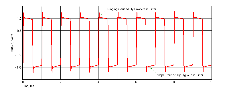
For reference, Fig. 4 shows the output waveform with a 1kHz squarewave input. The voltage is 1V peak (1V RMS). The ringing is the result of the sharp cutoff Chebyshev low pass filter, and the slope on the squarewave 'flats' simply shows that response does not extend to DC. Of course you can use a squarewave with a scope, but the rise and fall times are restricted to about 115mV/μs for a 1V RMS squarewave. It will also show slight ringing as seen above. These will not normally be audible.
This is a simple project, but the devil is in the details. Since the whole idea is to be able to measure low noise voltages, it must be in a very well shielded enclosure, and ideally supplied with a linear power supply to prevent SMPS switching noise from intruding on the measurement.
I mentioned above that R13 and C7 have to be mounted with very short leads so stray inductance doesn't cause issues, and the input circuitry should ideally be shielded from the filters. The DC filter shown in Fig. 1 (along with a good shield) is probably mandatory if you use switchmode supplies or plan on testing Class-D amplifiers. For the latter, you must use an external voltage divider to ensure that the maximum input is less than 5V RMS. The input has no protection, so there's a real risk of damage if you apply any voltage greater than ±15V.
It this something that everyone needs? For most, I expect the answer is "No", but for a fairly modest outlay you have a nice piece of test gear that will make noise measurements truly meaningful. It can be used with a scope, allowing you to see low levels without all the annoying fuzz on the waveform. Attempting to push a squarewave through it is unwise unless you understand what filters do to otherwise 'perfect' squarewaves, hence the response shown in Fig. 4. It will be used predominantly for removing noise, allowing you to measure the actual noise level of the device under test. Because it's an active circuit, it will add some noise as well, and this needs to be taken into account.
When noise voltages are added, it's not the simple sum of the two. Two equal noise sources don't double the noise (6dB), it's increased by 3dB - a factor of 1.414 for two noise sources. It's the square root of the sum of the squares. This is shown in a formula as ...
Ntotal = √ (N1² + N2² )
This can be extended for any number of noise sources, but that's not often needed. If you know that the filter circuit adds (say) 100μV of noise and you measure your test circuit and get 141μV, you now know that your circuit has an output noise of 100μV. I'll leave it to you to work out the actual noise, both for the filter and your circuit. As an example, a TL072 has a noise voltage of 18nV√Hz, or 2.55μV output noise for a 20kHz bandwidth unity gain stage, with the input shorted.
One challenge will be to determine if the filter is audible in a blind test. According to much of the audiophool dogma it should be immediately audible to anyone and everyone, but I've yet to test that myself. Having tested all manner of filters over the years, this filter should not contribute anything audible with any programme material, because it mimics the response obtained from many digital audio files. However, it's not intended for listening, but for making meaningful noise measurements. It can also be used for distortion measurements, but the highest usable frequency is 5kHz. Any harmonics beyond the fourth (20kHz) will be attenuated, so the results will be optimistic.
 Main Index Main Index
 Projects Index Projects Index
|