
|
|
| Elliott Sound Products | Project 223 |
 Main Index
Projects Index Main Index
Projects Index
|
Project 44 has been on the ESP site for many years, and while it certainly works as advertised (as it were) it's best described as 'utilitarian'. In particular, the voltage cannot be reduced to zero, and the lowest voltage available is around 1.25V. As it's based on the P05 PCB, there's not enough space for a truly decent heatsink, and it was only ever intended as a low-voltage, low-current supply. The design shown here still uses the LM317/ 337 regulators, but has been designed to allow you to get down to zero output, as well as obtain more output voltage and current. Getting down to zero volts requires a surprising number of additional parts, but they are all cheap and shouldn't cause issues for anyone.
This design isn't 'new' and parts of it are alluded to in the LM317 datasheet. The regulator needed is the LM317T, in a TO-220 package, rated for a load current of 1.5A. This is a complete design, and it includes current sinks at the output to draw the required IC current to ensure regulation. These can be altered easily if necessary, as some LM317T ICs may require up to 10mA output current to regulate. The use of current sinks allows for a readily available 10k pot for setting the voltage, something that is not otherwise possible.
In the article Bench Power Supplies - Buy Or Build? I discuss the relative merits of buying vs. building your own bench supply. Consider that the design here is as simple as it's possible to make it while ensuring that it performs well. There's optional (switched) current limiting, as well as that in the regulator ICs, so load fault conditions can be controlled if you're careful. Adding current limiter circuits increases complexity, but the switched version keeps the circuit fairly straightforward. The output current meter will also show if there's a problem, with the current rising quickly as the voltage is increased slowly.
Because you build this supply yourself, you get to choose the meters used. While I always prefer analogue meters, the case I designed is only 50mm high, and I elected to use DPMs because they would fit. They do have an advantage, in that you can get dual meters quite cheaply (make sure you get some spares though), and you can monitor positive and negative voltage and current simultaneously. It makes for a pretty neat design overall. I have a separate 5V supply, so elected not to include the 5V supply, and space inside the chassis is rather limited, and I didn't have space to include another transformer, rectifier/ filter and heatsink.

Despite the apparent complexity of Figure 1 (below), it's actually very straightforward, and the -1.25V supply, main regulator and output current sink can be built on Veroboard easily (See Figure 11). However, it also shows that even a 'simple' supply is not a particularly cheap exercise. The transformer is by far the most expensive single component, as you need at least a 150VA transformer to be able to get 25V DC at 1.5A. Don't be at all surprised to discover that you can buy a (single) power supply for less than the cost of the transformer alone!
Although the general idea is to obtain a ±0-25V supply, with two identical regulators they can be used in different ways. The normal configuration will be with the supplies in series, but they can be connected in parallel to get 0-25V at 3A, and can even be used independently. The voltage control and current limit switch will normally be dual-gang types, but they can also be separate, so each supply can be set to different voltages.
I avoided making the supply into a 'precision' dual-tracking design, as that only leads to more complications. Very few circuits are affected if there's a small difference between the positive and negative supply voltages, and even with an 'ordinary' dual-gang pot they will be close enough for 99.9% of circuits. If you really do need a precision supply, then the only sensible option is to buy one. Of course they aren't cheap, so you either learn to live with some imperfections or you spend a considerable sum to get a supply from a reputable supplier (eBay doesn't qualify).
Despite the apparent simplicity of the design (when viewed in small subsections as described below), a complete supply is a rather formidable undertaking. I know this from my own experience, as I built one so I still have a decent dual 0-25V power supply to use while I perform some much needed work on the one I've been using for well over 20 years. The new design was a great deal more work than I anticipated, not helped by the choice to build the case from scratch. I had almost everything to hand, but the decision to provide the option of series or parallel operation ended up creating far more wiring than I expected. Was it worth it? IMO, yes, but I was surprised by the complexity of the final product - particularly the wiring!
You need to be particularly vigilant with connections indicated as 'Gnd' or 'Com' (ground/ common). This is because they change depending on the way the outputs are switched. When the supplies are in series (to get ± supplies) the 'Com' is the junction of the negative connection for the 'upper' supply (#1) and the positive connection for the lower supply (#2). When in parallel, the 'Com' terminal is not connected, and the parallel supply is obtained between the +Ve and -Ve terminals.
The drawings have been updated to make this as clear as possible, but it's not particularly intuitive. Figure 8 now includes a diagram that shows both series and parallel connections in simplified form.
There are quite a few differences between this project and the (at the time of writing) 21 year old P44. One is the negative supply, which is designed to give a -1.25V reference for the positive regulator (and Q1). By having the opposite-polarity reference, VR1 (the voltage pot) can reduce the output voltage to zero. This is not possible without the negative supply.
Then there's the addition of trimpots. Because the tolerance of most pots is pretty poor, TP1 (1kΩ trimpot) is provided to allow each supply to be set to 25V with the voltage pot at maximum. The trimpots also allow correction for the IC's internal reference, which is nominally 1.25V, by can vary between 1.1V and 1.3V. Because the dual supply relies on a dual-gang linear pot, expect some minor differences in output voltage. The maximum difference I've observed is about 0.5V, which won't cause grief with any common circuit.
Next is the use of current sinks to allow the use of a readily available dual-gang 10k linear pot. Current sinks are used because they will draw the same current with a collector voltage of 25V or zero, something a resistor cannot do. Q1 is the current sink, designed to ensure that the output regulates properly with no external load. The datasheets for the regulators state that the minimum output current for regulation is 3.5mA ('typical'), but may be up to 10mA. Q1 is biased from the -1.25V low voltage supply, with R4 setting the current through Q1 to a nominal 6mA.
Finally, there are two separate regulators, which are identical. One is used for the positive supply, and a second for the negative supply. This requires separate transformer windings. It makes construction easier, because both regulators are the same. They are connected in series at the output, with the option to connect them in parallel if you need higher current. Be warned that the series/ parallel connection is straightforward, but it will be fairly easy to make a mistake, so care is needed. The output switching is most easily done with a relay, or three relays if you include the option for series/ parallel operation.
The low-voltage negative bias network uses a pair of capacitors feeding a bridge rectifier (which can use 1N4148 diodes if preferred), negating the need for an extra winding on the transformer (there will be a second winding, but it's used for the other supply). The peak current is limited by a pair of 220Ω resistors. The 'raw' supply is smoothed with a 220µF 25V electro, protected against over-voltage by a 15V zener, and fed to an LM337 to get a stable negative reference voltage. This network does introduce a small delay though, and the output voltage from the main regulator will rise to about 4V above the set voltage when power is applied. It doesn't last very long (about 35ms), but it's enough to damage low-voltage ICs unless you include a delayed switch-on after power is first turned on. See Figures 5/ 6 for a switching scheme that provides the required delay.
All diodes can be 1N4004 or similar, but I suggest that you use higher current types for D1 ... D4. 1N5404 types are more than acceptable. The filter is shown using a 10mF (10,000µF) capacitor, but you can use two 2.2mF (2,200µF) caps, separated by a 1Ω, 5W resistor. The ripple is slightly lower with a 10mF cap and there's less voltage drop. However, the 2.2mF caps will almost certainly be quite a bit cheaper, and the increase of ripple isn't a concern. Of course, you can use other values as well, but 2 x 2.2mF is the minimum I'd recommend. There will be two supplies, and both are identical.
One thing that is absolutely critical is the heatsink for U1 (U2 doesn't need a heatsink). The TO-220 package is not good for dissipating heat to start with, so ensuring the best possible thermal performance between the package and the heatsink is critical. I'm very reluctant to suggest a 'hot' (i.e. live) heatsink, so you need to make sure that your IC mounting is the very best you can achieve. Needless to say this eliminates silicone pads from the equation, as those you can get readily have poor thermal conductivity. My preference for the best thermal transfer is alumina (aluminium oxide ceramic), but they may be difficult to get. Because we're dealing with low voltages, the next best is probably high-temperature nylon - obtained by cutting up an oven bag (yes, really). It's extremely thin though, and the tiniest piece of swarf will puncture it. It must be used with thermal compound (aka 'thermal grease'), but it's actually very slightly better than Kapton. The heatsink also needs to be bigger than you thought, and/ or using a fan for maximum thermal efficiency.
Note the connections labelled 'Lim'. These are only used if you include the optional current limiter circuit shown further below. Rather than add the current limiter circuits, it's easier to use switched internal 'safety' resistors. They aren't particularly precise, but the idea is to limit the current if there's a fault on the board being tested. This option isn't shown, but switched 100Ω and 22Ω resistors should do nicely.
Pretty much the only meter I'd consider for a power supply is analogue, particularly for current. They don't have the apparent accuracy of digital panel meters (DPMs), but they are both immediate and intuitive. Just like having to press buttons to select voltage and/ or current is unacceptable for a bench supply, so are meters that you have to read, but can't do so if they're changing rapidly (especially current). Voltmeters can be digital, since they show the preset voltage, and this usually doesn't change other than under the user's control, or if the optional current limiter becomes active. Having said that, the unit I built does use DPMs because there wasn't enough space for analogue meters (my unit is only 50mm high, but the analogue meters I had to hand are 60mm).
This is not to say that you should not use DPMs (digital panel meters) of course. A dual meter with voltage and current displays can be obtained for less than AU$10.00 each, and these include a low-resistance shunt resistor that minimises voltage drop. A pair of these gives you a readout of voltage and current for each supply, at less than the cost of a single moving-coil analogue meter. They are also fairly small, so don't take up a great deal of front panel real estate. However, the cheap ones are slow, making precise voltage settings a bit of a chore.
While the addition of analogue voltage and current meters is useful, it's fairly expensive at about AU$20.00 each, and you also need shunts (current) and multiplier (voltage) resistors and calibration trimpots. If you want to add meters, Figures 2, and 4 (the latter for DPMs) shows how they should be connected. Only a single voltmeter is shown, and it will be necessary to check the internal resistance to determine the value of the calibration resistor. This meter is connected to either the positive or negative supply, and the switching is optional. You will need the switch if you choose to make two independent supplies, because each can be set to a different voltage. The voltmeter can be simplified if you're sure that the meter is accurate. If you use 50µA meters, a 500kΩ resistor with 25V across it will pass 50µA, and the error caused by the meter's coil resistance is negligible, at less than 0.06%.
Adding the ammeter is always going to cause some voltage loss, in this case, 75mV at 1.5A output, using 50mΩ shunt resistors (2 x 1Ω/ 1W resistors in parallel). While this is a small disadvantage, in reality 99% of all circuitry won't care at all. By switching the ammeter, it means that only one is needed for current, with another for voltage. The meter faces will have to be re-calibrated of course, and it's not particularly difficult to do with a scanner and printer. The new meter face can just be stuck onto the rear of the existing face with (thin) double-sided tape or a suitable adhesive. Make sure that you include positioning markers to ensure that the new meter face lines up with the original scale.
If you find that 50µA meters are unavailable, you can use 1mA (or 100µA) movements. The approximate values for 1mA meters are shown in Figure 3, designed to provide the same 1.5A maximum current reading, and 25V for voltage. Obtaining a 38.7mΩ shunt resistor will almost certainly be impossible, so you're relegated to using a fixed resistor and a trimpot to set the current. This is a method I've used countless times, and it works well. The same values can be used for current with 100µA movements as well. The voltmeter needs a series resistance of around 250k with a 100µA movement.
If you prefer to use DPMs, the following drawing shows the typical connections. While there are several different types available (all come from China of course), they seem to share the basic wiring scheme shown next. Accuracy is claimed to be ±1% for voltage and ±2% for current, but a few tests I did indicated that this is probably somewhat optimistic. Adjustments are provided internally, but they are minuscule single-turn trimpots, and accurate adjustment is likely to be tricky. My suggestion is to use two dual DPMs, with one for each supply. It's possible to use a single meter and switch it, but the extra complexity isn't warranted. Being able to monitor both supplies at once is a far better option, and lets you make the most of the DPMs. Using a single switched DPM is further complicated by the requirement to switch the supply as well. This cannot be shared between the supplies.
There are a number of different DPMs available, but the one shown is fairly representative. The heavy wires are for the current meter, and while it may look confusing with the red lead being the load return, it makes sense as it is (very slightly) more positive than the black lead. The yellow lead is for voltage measurement. These meters have a claimed current draw of 'less than 20mA' (one I tested drew just over 10mA), and the simple zener regulated supply ensures that there's still more than 20mA available even if the unregulated supply falls below 30V. R1 will dissipate close to 1W when the supply is unloaded, so use a 2W resistor.
With a maximum output current of 1.5A, a toggle switch can be used to turn the output on and off. However, a relay is a better alternative because you can then use a mini-toggle switch rather than a power type. Ideally, the relay will receive power via a delay as shown, which prevents the circuit from producing an over-voltage when powered on. If the supply cuts out in use (due to a low output voltage and high current), you can add a switched fan. Of course the fan can be on all the time, but the noise is annoying.
The delay can't be incorporated easily without a relay, and the bit of extra circuitry is well worth the effort. There will come a time when you have a low-voltage IC connected, and you'll forget to turn off the output before mains power is applied. A power supply should not damage your circuits, and the peace of mind is well worth the small cost of a relay and a few cheap parts. The simple regulator shown will do the job, or you could use an auxiliary supply. The latter is not worth the extra cost IMO. It's not cheap to include a separate supply, so a very simple regulator has been included, using a BD139 as the series-pass transistor. Q1 must have a heatsink, as it can dissipate up to 4W with 2 relays on and the fan running.
Power can be taken from either of the +35V supplies, but not both. If you use 24V relays and a 24V fan, current (and transistor dissipation) is reduced. I've shown the regulator (Fig. 5A) set for 12V output, and the 24V version is shown next (Fig. 6). 24V relays (and fans) have a lower current consumption, so less current is needed for switching. The 24V relays I used have 1,400Ω coils, so will draw 17mA each, and ~65mA for an 80mm 24V fan. Total current is around 100mA, vs. 188mA for typical 12V devices. Note that the auxiliary power supply is derived from one of the main rectifier/ filter sections. It doesn't matter which one, and although a 'GND' connection is shown, it's not connected to the chassis or anything other than the relays and fan.
The delay circuit ensures that the relay remains off for about 2.5 seconds after power is turned on. When DC is available after power is turned on, C2 charges via R2, until the voltage across the cap reaches around 5.7V (12V version) or 12.6V (24V version). Q3 starts to turn on, and turns on Q2. Switching action is quite fast because the circuit has very high gain, so the relay will activate quickly. I contemplated adding hysteresis to get true 'snap-action', but it's not necessary. D1 is used to discharge C2 when power is turned off. The delay is independent of Sw2 (DC On). If that's on when power is applied, the DC relay will not activate for 2.5 seconds. Once the timer has applied DC to the relay (+12V Dly or +24V Dly), the switch action is immediate.
The two thermal switches are the best (and simplest) arrangement, although you can keep the whole process manual, using a switch. You'll know the fan is needed if the IC regulator's thermal shutdown activates, removing one or both supplies. Note that there's no circuitry to detect if one supply has shut down and automatically shut down the other. This isn't especially complex but it adds more parts and wiring to a project that's intended to be easy to build. The thermal switches are shown as an option. Normally open switches are readily available, with a variety of temperature options. My recommendation would be to use a switches with no more than a 45°C operating temperature, with one switch right next to each regulator. The switches are simply paralleled, so if either regulator gets hot, the fan is turned on.

In the interests of simplicity, I wasn't going to include variable thermal sensing to turn on the fan, but the thermal switches I ordered took too long to arrive, and I had 10k NTC (negative temperature coefficient) thermistors and everything else available. The switching circuit has hysteresis, so after the fan turns on, the heatsink temperature has to fall below the trip point before it turns off. Q1 is a very common small-signal N-Channel MOSFET, and the trip temperature is adjusted with the trimpot (VR1). R1 provides positive feedback to ensure fast switching and provide hysteresis, and it can be increased in value to provide a narrower temperature range. R4 ensures that the zener reference voltage is stable.
The circuit can be used with a 12V supply, but the fan current is much higher. R3 must be reduced to 1k to provide sufficient base current for Q2. The remaining 3.9k resistors don't need to be changed. The feedback resistor (R1), trimpot and thermistors also remain the same. Adjust the trip temperature to something you're comfortable with (I suggest no more than 45°C). This circuit is (deliberately) fairly basic, and is also a useful exercise in analogue design. I could have used an opamp as a comparator, but it would end up being no simpler in real terms. Be aware that if both regulators get hot at the same time, the fan will turn on at a lower temperature. This isn't a limitation in practice.
If you want to add the option for series/ parallel operation, the above shows the switching. By using relays, you don't need heavy-duty panel switches, and it makes wiring easier because the relays can be located right next to the output terminals. RL1 is the same as shown in Figures 5 & 6 - it's not an extra. Note that although the 'common' terminal is shown connected to 'GND', this is not connected to the chassis or mains earth. All three relays should be rated for at least 5A to ensure low contact resistance. You could get away with 2A relays, but they will be taken close to their limits.
The simplified drawings to the left show how the relays connect the two power supplies. Mostly they will be in series to get a ± supply, but if you need the maximum possible current they can be connected in parallel. The 'Com' terminal is connected to the -Ve output for a parallel connection.
The other two relays select Series (RL3) or Parallel (RL2) operation. The wiring for these is a bit fiddly, so make sure that you follow the circuit carefully. When switched to Parallel mode, the negative output and common/ GND are joined together, and either terminal can be used. If analogue metering is included, it will typically come after this circuitry, and you'll need to calibrate the current meter to 3A rather than 1.5A. If the series/ parallel switching isn't needed, then just use the Figure 5/ 6 circuit, and permanently join the negative terminal of Supply 1 to the positive terminal of Supply 2. This is a series connection, and you can see that being switched by RL3.
One thing to be aware of with a parallel connection ... the output voltage will always be the higher of Supply 1 or Supply 2 (even a few millivolts is enough). The higher voltage supply will deliver most of the current until it reaches its current limit, at which point the other supply will start to deliver current. While it's possible to force both supplies to share the current equally, this would add complexity for little net benefit.
Note: When switching from series to parallel or vice versa, always reduce the voltage to minimum before doing so. Also, make sure that the output leads are properly configured so the DUT isn't damaged by excess voltage.
One option that you may wish to include is a current limiter. I've designed this as a separate 'module' that can be included or not, depending on your preference. It can be added later if you include links on the Veroboard that you can use to connect the -1.25V supply and the 'Adj' terminals on the regulator ICs. The incoming DC is passed through the current limiter before the regulators when (if) you decide that limiting is a good idea. I've only shown three ranges - nominally 33mA, 330mA and 'Max', which allows the maximum output from the regulator ICs. With typical 2-pole rotary switches, you can have up to six ranges, but IMO that's not necessary.
An integrated current limiter requires great care to ensure stability as it's a feedback circuit. When used alongside the LM317, it's surprisingly easy to create an oscillator when current sense circuitry is added. The tendency to oscillate is suppressed with C10 (10nF). Be aware that the extra dissipation in the regulator will cause problems if you include a higher current range. The 1.75Ω resistor (RL2) was obtained with 2.7Ω in parallel with two 10Ω resistors, also in parallel (5.0Ω). You must be prepared to experiment with the limiter resistor values, as they depend on the VBE of the sense transistor. The limiter can be improved, but only at the expense of greater complexity (which I deliberately avoided).
A simple current limiter only needs a few low-cost parts. The design shown is switchable, with three settings. The limits can be changed by varying the value of the current-sense resistor(s). The current is determined by the base-emitter voltage of Q2. If the voltage across the limiting resistor exceeds ~540mV, the transistor turns on, in turn turning on Q3, which pull the regulator's 'Adj' pin towards the -1.25 volt reference. Note that the power supply transformer, rectifier and filter sections aren't shown.
There is no 'Limit' LED, as the available current is too low (less than 100µA). Running wires to and from the front panel is also likely to cause instability. You'll know when the limiter is active, because the current and volt meters will show no increase if you try to increase the voltage. The lower limit of ~33mA is sufficient to prevent most failures, but some parts can still be damaged if you're not very careful when testing a new build.
The current limiter is designed to have absolute precedence, so it doesn't matter what the voltage setting is, the limiter will only allow the preset current, and it adjusts the voltage regulators to suit. This reduces (but sadly does not eliminate) the likelihood of oscillation, which can be very hard to cure. Sensing the current before the regulator means that there's a small error, because the current sense resistors also have to provide current to the regulators and the current sinks at the output. The error is only about 6mA and has been factored into the design. Like the regulator, there are two identical limiter circuits, with a double-pole switch to control both at the same time.
If you wish to add ranges or modify those I suggest, the resistor value is simply (and approximately) 540mV divided by the current. For example, a 500mA range would use a 1Ω sense resistor. Care is necessary though, because the regulators are only in a TO-220 package, so the maximum power dissipation is limited to about 20W. If you try to provide 500mA into (say) a 1Ω load, there's close to 35V across the regulator IC, so it will dissipate 17.5W. This is close to the thermal limits of the package, and the IC will get hot unless your heatsinking (and fan) are up to the task.
The current sense transistor is also subject to thermal effects. If the transistor gets hot, the base-emitter voltage falls by about 2mV/°C. This can be used to your advantage, by mounting the sense transistors right next to (or on top of) the regulator ICs. If they get hot, the current is reduced. Based on a simulation, if the transistor gets to 70°C, the current is reduced from 330mA to 250mA. This reduces IC dissipation from ~12W to 9W. You won't see that much reduction because the transistor's junction won't reach the case temperature, but it's something that can be used to your advantage.
If you set the main supply to 5V output and draw 1A, the regulator will try to dissipate close to 30W, and it's really hard to get that much heat out of a TO-220 package. If that's something you think you'll need often, it's better to use a lower voltage transformer and build a 'floating' 5V supply that's independent of the variable supply. This is provided in many 'true' lab supplies.
If you do a fair bit of work with digital 'stuff', whether TTL, CMOS or Arduino and similar microcontrollers, a separate 5V supply will be handy. The 7805 can deliver up to 2A fairly easily, and this is sufficient for most 'typical' digital loads. I suggest that the GND terminal is not connected to the main supply 'Com' (common), nor to the chassis. The output should be floating as this gives greater flexibility. Current limiting is possible, but it's usually expected that you'll test your circuitry with a current limited supply before connecting it to a high-current fixed supply. Most commercial supplies with a separate 5V output don't include current limiting. If you already have a 5V supply, this section can be omitted.

The circuit is very simple, and I used the same filter parts as the main supply other than R1, which is reduced to 0.47Ω. If you expect to draw 2A from the 5V supply, the transformer needs to be rated for 9V at a minimum of 4A (36VA). This might seem like overkill, but it isn't, as the AC current is typically at least 1.8 times the DC current. A larger transformer will have better regulation. You can expect the unregulated DC to be around 13V with no load, falling to 10V at full load.
It's not possible to ensure that a design such as that suggested will work properly based only on a simulation. As a result, I've built a pair of boards to verify that the circuits work as claimed. It does, but having built and tested it, the current limiter proved to be a problem. I guessed that this would be the case, because adding a pair of high-gain transistors is always a recipe for oscillation when combined with a wide-band linear circuit such as a regulator IC. The oscillation was cured by adding C10, although the simulator refused to accept that this was sufficient. No great surprise there either.
The other thing that the simulator got wrong was the current limiting. In theory, we know that transistors conduct with 0.65V from base to emitter, but in this circuit the first limiter transistor starts to conduct with about 540mV base-emitter voltage. This means that the limiting resistors have to be reduced in value or it limits prematurely. This is reflected in the schematic for the limiter (Figure 9).
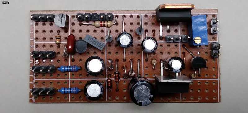
In the photo you can see that it's not too difficult to make a very compact layout. The one shown includes the main regulator, the -1.25V supply and the current limiter. The connections on the left (top to bottom) are DC input, ground, AC1 and AC2. The connector at the top is for the current limiting resistors. The main regulator (LM317T) is at the top right, and the -1.25V regulator (LM337) is at the bottom right. The compete board measures 32 x 65mm. Naturally there are several cut tracks and a couple of track-to-track links under the board.
Having built these, I found that I had to remove the tab from the LM337 so I could access the screw holding down the LM317, so I suggest that you make the board a little longer and offset the regulators to allow easy access. No, I didn't think of that when I wired the Veroboard layout, but found out very quickly when it was time to screw the regulator to the heatsink.
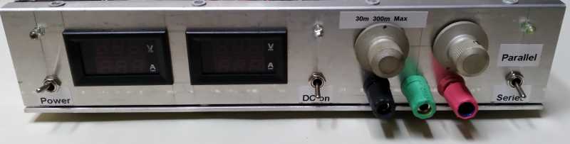
The front panel looks pretty much as you'd expect. I didn't include the 5V supply because I already have one built into my workbench. Having played with it and run a suitable barrage of tests, I can safely say that I still dislike the digital meters. Not because they don't work (they are pretty good as far as digital meters go), but setting the voltage is a pain, because like all (cheap) digital meters, the display doesn't update instantly, so there's a lag between turning the knob and seeing the actual voltage. I can live with it of course, but analogue meters are far more user-friendly.
The insides are ... compact. I included every section described, including the thermistor fan controller, series/ parallel switching, the regulator and delay circuit and current limiting. The three ranges are (nominally) 30mA, 300mA and 'Max'. The actual current is a little higher than the target, but is more than acceptable to prevent things from being destroyed.
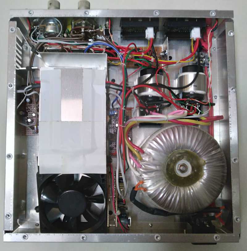
The heatsink tunnel is under the white tape and aluminium cover, on the left side. Because the case is only 50mm high, the fan is at an angle, and has an intake vent at the back, with a ducted outlet on the right panel (which is at the top left as the photo is taken from the rear). You may notice that I used cable lacing cord rather than cable ties, using the method I learned decades ago. I think it looks much nicer, and I've never been a fan of cable ties. The circuit was not easy to wire up. There's far more wiring than I expected, partly because I used a tunnel heatsink which means that wires have to run back and forth. All in all, I'm reasonably pleased with the end result, and it was nice to discover that the LM317 regulators can provide up to 3A when the IC's differential (input to output) voltage is less than 15V.
As noted in the referenced article Bench Power Supplies - Buy Or Build? building a supply is an expensive undertaking. Even a simplified and relatively low power design such as that shown here will cost more than a typical 0-30V, 5A supply sourced from eBay, but that will be single-polarity only. However, there is one thing you get that you can install that you don't get with commercial supplies, the option of analogue meters. Seeing fluctuating current on a digital meter is impossible, and it's even hard to see if the current is increasing rapidly because digital meters do not let you see rapid variations. Of course you can use an analogue multimeter, but not too many hobbyists even have one any more.
While this design lacks fully variable current limiting, tests are easily made by either the simple switched current limits or 'safety' resistors in series with the positive and negative outputs. The value depends on what you're testing, so you might use 10Ω for a power amp's first test, or 100Ω for a small opamp circuit. The use of safety resistors is covered in almost all construction articles, and it remains a simple but effective way to prevent the destruction of parts. You can include the safety resistors internally, and select the required value with a switch. This is better than having extra parts lying around on the workbench. The current limiter thresholds suggested are suitable for most tests.
One thing that you usually can't do with a modern switchmode bench supply is fix it if it breaks. Schematics are not available, and most make extensive use of SMD parts and are pretty much inscrutable inside. If you build your own, you can make changes to the design, fix it if it ever fails, and gain some skills along the way. You won't save money though, unless you make the comparison between a home-made and a 'top-shelf' commercial unit. Most of the units you can get cheaply are only a single supply, but you may be able to pick up a 50V supply and use a simple voltage splitter (aka 'artificial earth/ ground') circuit to obtain positive and negative supplies.
It's should be fairly obvious why I haven't published a design for a complete dual-tracking power supply with full current limiting and all the bells and whistles that people seem to expect. This project is about as simple as it can be, while allowing for a reasonable output voltage range at up to 1.5A. Beyond a certain point it becomes almost impossible to build a power supply without a dedicated PCB. This remains a possibility, but it won't be in the near future. Because the circuits are still relatively simple, the various 'modules' can be built using Veroboard, as I did. Each schematic can be treated as a separate module, and are interconnected fairly easily (albeit with a considerable amount of wiring).
LM317/ LM337 Datasheet
Various ESP articles
| Main Index
Projects Index
|