
|
|
| Elliott Sound Products | Project 190 |
It's not a particularly common requirement, but I have been asked about it, and decided that what little information is on-line is somewhat lacking in details and/ or reasoning. Dynamic mics can simply be shorted out (between pins 2 and 3 of the XLR connector), and while that approach might be ok with phantom powered (P48) supplies, there may be some noise if the current in each signal wire is not identical. Shure [ 1 ] has a published circuit that is the basis for the circuit shown here (not that there are many alternatives).
We normally expect that the DC voltage on each line of the mic cable will be the same with respect to Pin 1 (ground), however, component tolerances and other factors will combine to make this expectation unrealistic. The level from a microphone varies widely, being anything from a few millivolts to almost a volt - depending on the source being picked up by the mic. The voltages on Pins 2 and 3 only need to differ by a small amount (say 1%) to generate a signal of up to 480mV when the two leads are shorted. That's a large signal, even if the mic output is high.
So, if we can't apply a direct short, it needs to be done using capacitance. A high value is necessary, because most mics have a fairly low output impedance, generally less than 200 ohms. Note that shorting the output of a microphone (whether dynamic or phantom powered) will cause no harm to 99.9% of microphones, because they require protection from the phantom power anyway. If you are concerned, contact the mic manufacturer to find out if it's alright.
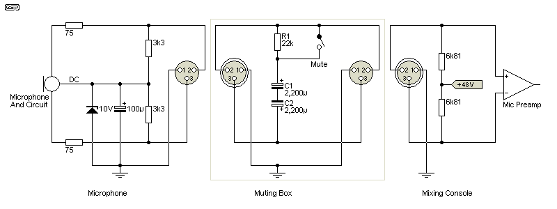
Figure 1 - Simple Shorting Circuit For Phantom Powered Mics
For clarity and so you can see how it all works together, the above drawing shows a 'representative' phantom powered microphone, the 'Muting Box' itself (centre) and the way phantom power is applied within a mixing console or mic preamp. Because the DC offset polarity is uncertain, two 2,200µF 6.3V electrolytic capacitors are wired 'back-to-back', so absolute polarity doesn't matter. The 22k resistor ensures that the voltage across the caps stabilises, so it doesn't cause a loud 'bang' when the switch is operated.
In use, the muting box can be on the floor, using a foot switch (push-on, push-off) as used with guitar pedals. Alternatively, it can be mounted on the mic stand, and can use a mini-toggle switch to mute the mic. No attempt has been made to provide an indicator LED, as the phantom supply current budget is too low (an absolute maximum of around 10mA is available). It could be done using a high brightness LED, but mostly it shouldn't be necessary.
If you insist on an indicator, I recommend using a 9V battery and a high brightness LED, keeping the current to no more than 2mA. This has some nuisance value, as you'll need a double-pole switch (one to mute, the other to turn on the LED). Most high-brightness LEDs will be acceptable with a 3.9k series resistor if you wish to add an indicator, but some may be too bight. If that's the case, use a higher value resistor in series with the LED.
Note that the box should be aluminium or steel, and must be connected to Pin 1 of the XLR connector(s). Using anything else could lead to hum pickup, although a plastic box can be lined with aluminium foil (use contact adhesive to stick it firmly to the inside). Making a reliable connection to aluminium foil is not easy - you will need to use a metal thread screw and nut with a wire lug to ensure reliable grounding. Inputs and outputs should be XLR, using female for the input and male for the output. This ensures that normal mic cables can be used.
Because the circuit uses capacitance to 'short' the mic signal, this inevitably means that attenuation is lower at low frequencies that at higher frequencies. With a 150 ohm mic, the level at 10Hz is only reduced by 20dB, but at 20Hz that's increased to 25dB, and by 40Hz it's 28dB. The ultimate rolloff is 6dB/ octave, so over most of the (vocal) audio band the signal is more than 40dB down. That's not perfect by any means, but you'll get an additional 6dB of attenuation by doubling the capacitor size. Because only low voltage caps are required, they won't be especially large.
Performance is also improved if the mic has a higher output impedance, but for most practical applications you'll find that the attenuation will be more than sufficient with the circuit as shown. You'll hear a dull 'thud' through the speakers if the mic is dropped, but that's not really a recommended test method.
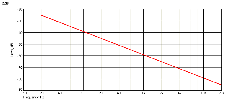
Figure 2 - Attenuation Vs. Frequency (150Ω Mic, 1,000µF)
The attenuation vs. frequency graph is shown above. At most frequencies as interest, the attenuation is greater than 30dB, so only very low bass notes will get through, but greatly attenuated. This arrangement is just as applicable for dynamic mics, although they can simply be shorted. The benefit of using a circuit like that shown is that it's 'universal' - you don't need to have different mute boxes for different microphone types. You do need to be aware that attenuation is reduced with mics having a lower impedance, but if that's of any concern, use larger capacitors (or use four in series parallel).
 Main Index
Projects Index
Main Index
Projects Index