
|
|
| Elliott Sound Products | Project 185 |
 Main Index
Projects Index Main Index
Projects Index
|
Polarity testing for individual loudspeaker drivers is usually easy enough if they are not installed in an enclosure with a crossover wired in, but it becomes much more difficult if you want to verify that they are correct once wired up and inaccessible. A 1.5V cell can be used with (almost) any moving coil driver, and if the positive terminal of the cell is connected to the positive terminal of the speaker (and negative to negative of course), the cone will move outwards (air compression) with correct polarity.
This works with most tweeters as well (the power is under 300mW for an 8 ohm tweeter), but is obviously not possible with ribbon tweeters. Nor is it possible (at least not without an oscilloscope) to verify that the entire signal chain retains the correct polarity. While it's not essential to have a signal that maintains the 'correct' polarity (it's generally inaudible, despite claims to the contrary), it is considered to be the 'right' thing to do.
It can be especially difficult to verify that microphones are correct. Most are, but you generally have no way of knowing for sure. In some cases, it may be due to a miswired mic lead, or the mic itself may have been 'repaired' by someone who was careless about polarity. This is particularly important when two (or more) mics are used on a single instrument, a common practice with pianos and some other larger instruments. An out-of-phase microphone will make the sound very un-natural, with reduced bass output and/ or a 'strange' sound stage (for stereo setups). During testing I discovered that a 'high quality' electret mic (with internal battery) I have is out of phase. I never knew that before, so it shows that testing is worthwhile.
The project shown here is fairly simple, and uses the most common signal for this kind of test - a positive pulse, which can be as basic as a simple push-button to discharge a capacitor into a speaker (but there are caveats to this as seen below), or a train of positive pulses with a repetition rate of around 1 - 2Hz or so. Whether you need the continuous pulse provision or not is up to you. If you can get a suitable push-button switch (see below to find out what is 'suitable'), the single pulse option works well and saves a few parts.
There are very few polarity tester circuits described anywhere on the Net, despite an obvious need - especially for live sound and recording environments. There are several you can buy, but some are surprisingly expensive. The polarity of mics can be changed simply because of an incorrectly wired lead or a repair, and reversed mics can play havoc during live sound or recording sessions. Many mixing consoles have a 'reverse phase' switch (by whatever name), but it's always helpful if you know in advance that the 'normal' position really is 'normal'.
Polarity testing is often required with car audio installations as well. The wiring to various speakers may not be colour coded, and it can be difficult to work out which is which. Both leads usually sit at ½ battery voltage (nominally 6V), and neither can be connected to the vehicle's chassis without damaging the amplifier. A simple positive repeating pulse signal can be recorded on a medium that's supported by the car's inbuilt entertainment system. The detector can then be used to determine the polarity of each speaker in the system. For decent sound, the speakers should all be in phase.
Naturally, the pulse generator ('transmitter') is the fist thing needed. This can be in a separate box if you prefer, but mostly it's better if it's in the same box as the receiver (who wants to mess around with two separate boxes?). There are two choices - either a single pulse initiated by a push-button, or an oscillator that provides very narrow (less than 1ms) pulses at a suitable repetition rate. Both are shown below. The opamp used is an LM358 - these are low cost, low power types that allow the output to go to 'ground' (zero volts, within a few millivolts). There are others that may be suitable, but they will be harder to get and usually considerably more expensive. The LM358 is not a hi-fi opamp (I don't recommend it for any circuit that handles audio signals), but it's perfect in this application.
The 'power on' LED (LED3) is shown with a 2k2 current limiting resistor, but if you use high brightness LEDs throughout the series resistor can be increased. Up to 10k is fine with most high brightness LEDs, and this will reduce the current. With the 2k2 resistor each LED (see Figure 3 for the other two) each will draw around 3mA, so even with the 2k2 resistors the total current drain will still be less than 10mA in normal use. Note that all diodes (in all circuits) are 1N4148 or similar.
Figure 1 - Single Pulse Generator Circuit
The simple version simply charges the capacitor (C4) and it will reach close enough to full charge in about 2.5 seconds. When the button is pressed, C4 is discharged into the into the internal (used for mic testing) or external speaker. VR1 provides a variable level signal to the line output connector. During testing, I found that one thing that is absolutely critical is the switch. It must make perfect contact each and every time, with no contact bounce. This is a great deal harder than it sounds, and I tried several different switches, with at least two of them often providing a negative output on the oscilloscope when I knew perfectly well that it should have been positive. This might seem improbable, but a speaker is a reactive load, and even a few microseconds of contact bounce has a huge effect on the results you see. Consequently, I can't recommend most push-button switches because they may be erratic ... but only some of the time (which is worse!).
In particular, avoid 'snap-action' switches (especially those that you might expect are specifically intended for this type of application!). Toggle switches are generally no better, although one (very old and overly large) worked reasonably well. Mini 'tactile' switches (as seen in the inset in Figure 1) seem to work well, despite the snap action which is reason for the 'tactile' nomenclature. Unfortunately, you'll have to be a bit inventive to mount this style of switch. 'Ordinary' push-button switches that close with no 'snap' should also be fine. These rely on simple metallic contact and close at the same rate as you press the button. A firm press ensures good contact with no contact bounce.
R23 (10Ω) has been included because without it, the pulse will be far too long as C4 would be discharged into 10k (around 2.2s discharge time, instead of a more sensible 2ms with 10 ohms). I recommend that you use an oscilloscope to measure the signal going to a loudspeaker ... not the resistor, as that isn't reactive and you may not see the signs of problems. Switching must be clean - a single pulse with no 'hash' at the beginning which is indicative of contact bounce. It may be necessary to test a few different switches until you find one that works reliably ... every time!
The following circuit may be preferable for a variety of reasons. In particular, there is no issue with switch contact bounce. It sends a continuous stream of pulses that should make setup easier. The pulse duration is consistent (around 2ms), regardless of load impedance. In either case, ensure that the line level control (VR1) is set to minimum before connecting it to an amplifier or preamp input, because the pulse is a fairly high level (at least 6V peak!).
Figure 2 - Pulse-Train Generator Circuit
This version generates a pulse train with a repetition rate of about 0.6 seconds (1.67Hz), which also drives the speaker and 'line' output connector. This is a good option, because you don't need to worry about contact bounce with a simple switch, and the output pulses are of entirely predictable duration and polarity. Of course, it's also more complex which will deter many constructors. Although I did build it, I'd be perfectly happy with the version shown in Figure 1, which I used for all initial testing.
I have to leave the internal speaker to the constructor. It will typically be a small (around 50mm diameter) type, and the availability of suitable types is somewhat variable, depending on where you live. Something that's easy to get here may not be available elsewhere (and vice versa). The impedance isn't particularly important, but less than 8 ohms is not advised. One option that I tried is a small car tweeter (these are often available as an after-market accessory, shown in Figure 9). The one I used is small, about 35mm total diameter, and it works very well (see Figure 9). The high frequency pulse is sufficient to get a 40mV peak from a run-of-the-mill dynamic microphone.
The connector used for the 'line level' output depends on the type of system, so will typically be an RCA connector for hi-fi, or an XLR for professional systems. Optionally, you can use a jack socket, either as well or instead of the other connectors. Different people will have different ideas as to what they prefer, so this is left to the constructor to decide. You can have as many (or as few) connections as you like, but obviously only one should be used at any one time. The external speaker output is probably best suited to using a pair of banana sockets/ binding posts. The internal speaker should be turned off when the external speaker is in use.
If you prefer, there's no reason not to include both the single pulse and the pulse-train circuits. I can't see any reason to do so, but it's an option that can be incorporated without too much additional switching. I leave this to the constructor, but personally I wouldn't bother.
By including an XLR output (male), leads can also be tested to ensure there is no cross-wiring (pins 2 & 3 swapped at one end for example). The other end of the lead plugs into the external mic input shown in Figure 4, and the gain can be reduced to the minimum. A good lead will show a positive pulse response, and if incorrectly wired it will show no response at all. While it's possible to add more circuitry to verify that everything is as it should be, you can simply use a microphone to test leads - if a lead is cross-wired you'll get a negative reading, and if either signal lead is open you won't get a reading at all. This circuit does not verify that the shield (pin 1) is connected though.
Next, we need to look at the receiver circuit. This is more complex, because it has to be able to pick up the pulse and decide if it's positive or negative. The 'line' input is for testing electronics, and (somewhat predictably) the mic input is for testing microphones. The gain of the detector is fixed - it will detect pulses of ±220mV. It's used without additional amplification for the internal electret microphone. For an external mic, gain is necessary (see Figure 4) and it should be increased until reliable detection is achieved. It doesn't matter if gain is too high, as the detector will still only respond to the polarity that arrives first.
The circuit must then decide whether the received pulse is positive (green LED) or negative (red LED). Since speaker diaphragms can (and do) waffle around a little after an impulse, the detector has to determine which pulse polarity arrived first, and ignore any subsequent pulses of the opposite polarity.
There are several ways this can be done. One commercial unit [ 1 ] I looked at uses a pair of 4013 CMOS 'flip-flops' (D-Type latches), but the circuit is a little convoluted. Another [ 2 ] uses a CMOS quad NAND gate (4011), which is simpler. I've chosen a simple arrangement using a 4093 CMOS quad Schmitt NAND gate, which works well and is very cost effective - even if you have to buy the 4093. The Schmitt trigger action means that the detection thresholds are better defined, and the hysteresis ensures that there is less chance of the LED flashing - it should remain steady as long as the receiver detects pulses of either polarity. Depending on the speaker you use, the first pulse may only last for 100µs or so, which means the circuit has to be fast enough to detect the pulse.

Figure 3 - Pulse Receiver & Decoder Circuit
The receiver/ decoder uses an internal electret microphone, followed by a polarity detector. U2 is configured as a window comparator. The input is biased to a nominal voltage of 4.5V, with the upper threshold voltage (set by R10, R11 + R12 in series) being 4.71V, and the lower threshold (R10 + R11 in series and R12) being 4.29V. When an input pulse exceeds either threshold, the respective output goes high. U2A detects a positive (in phase) pulse, and U2B detects a negative (out of phase) pulse.
So, a positive pulse causes the output of U2A to go high momentarily, which charges C6 via diode D3. Because there is a high value resistor (10MΩ) to discharge C6, U3A will turn on and stay on for at least one second, and the cross-coupling from U3A to U3B is used to ensure that U3B cannot turn on even if a negative pulse is detected, provided U3A is low. The circuit is only interested in one thing - which polarity pulse arrives first. The same pulse detection and lockout arrangement is used for negative pulse detection (U2B), and if U3B turns on first it automatically disables U3A by another cross-coupled circuit.
The unused inputs of U3C and U3D should be tied to ground (pins 8, 9, 12 and 13). If desired, U3C and U3D can be used in parallel with U3A and U3B respectively. This makes wiring much harder and isn't necessary. If you need more LED current, R15 and R16 can be reduced, but you may need to add a PNP follower to the outputs of the 4093. The bases go to the outputs, collectors to ground, and emitters to R15 and R16. This will allow a LED current of 15mA or more (with R15 and R16 reduced to ~ 470 ohms).
With the values shown, a peak input (from any source) of ±220mV is enough for it to detect the pulse. Based on my tests, no preamp is necessary for the internal mic, and the input from almost any source (other than an external microphone) is more than sufficient to get a reading. During tests, I used an electret capsule about 20mm from the speaker cone, and even with only a 5V pulse to the speaker I measured a peak output from the mic of over 400mV. See Figures 5 and 6 to see the responses obtained during tests. I used a generic 10mm diameter electret - you don't need a high quality unit, because it's just part of a test set to determine polarity. This means that you don't need any gain for the electret capsule, but you do need much more gain for external microphone tests.
While it is theoretically possible to use the internal speaker as a microphone, the output level would be very low, and it needs a very high gain amplifier to get a signal that's large enough to trigger the detector circuits. This wasn't considered worthwhile as it increases complexity. Electret mic capsules are inexpensive and have fairly high output, so no additional amplification is needed to get reliable detection.
After a test, the LED that was illuminated will turn off again after about one second. If the pulse train circuit is in use, the continuous pulses will keep the appropriate LED on until the test is terminated. The unit can be used in 'self-test' mode, by ensuring that the internal speaker and microphone are both turned on. You may need to place the front of the tester near an acoustically reflective surface to get the proper reading.
Figure 4 - Input Connections & External Mic Preamp
If you need to test microphones, you will need the preamp, as the signal level will be far too low without it. The external mic preamp has a variable gain (up to 50, or 34dB), and when used it should normally be set fairly low. You need only enough gain to ensure that the detector can get sufficient signal so that it can be decoded. The mic preamp uses the second half of U1. The capacitor values (C9 and C10) may look to be on the low side of normal, but the input impedance is high (50kΩ) and we don't need low frequency response. Even with the values shown, response extends to 64Hz which is more than acceptable.
Note the protective circuitry at the external input connector. This is necessary if one is testing power amplifiers (or even preamps), because the output level can easily exceed the maximum allowable (±4.5V nominal). The diode protection will not save the inputs from continuous power from a 1kW amplifier, but it will be sufficient for the intended use - pulse testing to determine polarity. D9 is there because without it, a high input level can cause the decoupled 9V supply to rise to a potentially damaging voltage. The output level (via VR2) only needs to be set high enough to get a reliable reading, and anything more is not necessary.
If you include a mic connection, it will ideally be an XLR. The wiring is shown for an unbalanced connection, and the XLR pinouts are correct based on all modern standards. Pin 3 was used as the 'hot' lead in some equipment from the 1970s or so, but that has never been the correct wiring. Pin 2 is 'hot' (aka 'positive'), Pin 3 is 'cold' (aka 'negative'), and Pin 1 is always earth/ ground. The terms 'positive' and 'negative' refer to the voltage produced by the microphone when the diaphragm is pushed inwards by a sound compression wavefront. Since the output is always AC, these terms can be somewhat confusing to newcomers. Should you use a stereo jack socket for the microphone, the tip is 'hot', ring is 'cold' and the sleeve is earth/ ground.
There's no provision for phantom power, so 'condenser' (i.e. capacitor) mics can't be tested without an external phantom supply. It can be done with batteries and a couple of 6.8k resistors, but high voltage batteries such as 22.5V (412A) alkaline batteries are fairly expensive and not so easy to come by. You need two to get a reasonable phantom power voltage, or you could use 5 × 9V batteries which will also work. The benefit of using 9V batteries rather than something more specialised is that you can get them anywhere, but they do take up a fair bit of space.
The following two oscilloscope traces were obtained using the Figure 1 pulse generator, along with a microphone wired as shown in Figure 3. The supply voltage was only 5V, but the results are unambiguous. These were obtained using simple push-button trigger - results with a 'proper' snap action push-button were not only ambiguous, but are best described as useless. Indeed, it was during the physical test phase of the project's development that I found that switch contact bounce was so severe that a useful (and predictable) output signal was difficult, and requires a switch with zero contact bounce. All traces shown were obtained using the 'mini tactile' switch as shown in Figure 1. No other switch I tested was reliable enough.
Figure 5 - Small Speaker (100mm) Test Results
As you can see, even with no preamp, the mic can deliver at least 400mV with no difficulty. The mic was positioned about 20mm from the speaker's dustcap, and the output is very clean and will be detected reliably. The speaker is underdamped after the initial pulse. Note the low-level, negative polarity signal after the pulse is finished. This is due to the cone returning to its rest position.

Figure 6 - 25mm Tweeter Test Results
A 25mm dome tweeter gives a great deal more output, because the pulse waveform is predominantly high frequency. You can see why it's essential to provide the 'lockout' circuitry, as the microphone picks up a negative pulse with even greater amplitude than the 'true' positive pulse (along with some ringing). The latter shows up because the tweeter has so little damping and due to the very fast risetime, there is almost certainly some dome break-up (the 'resonance' frequency is completely wrong for the tweeter used). The width of the initial pulse is only 100µs, but this is not a challenge for the detector to resolve.
Figure 7 - 2-Way Speaker With Crossover, Tweeter Response
As mentioned above, I tested a 2-way speaker cabinet (with crossover network) and obtained the above result for the tweeter, and the response below for the woofer. This particular box uses a 6dB/ octave series connected crossover network, so the impulses are correctly polarised. This will not always be the case.
Figure 8 - 2-Way Speaker With Crossover, Woofer Response
If the crossover used a 12dB network, one driver must be connected with reversed phase because the crossover network causes the outputs to be 180° out-of-phase. When this tester is used, you should see the tweeter and woofer show opposite polarity. The 180° phase shift is a 'steady state' condition that takes one full cycle before the phase relationships are properly established. The impulse is too short for this to occur (and it's not a 'normal' audio signal).
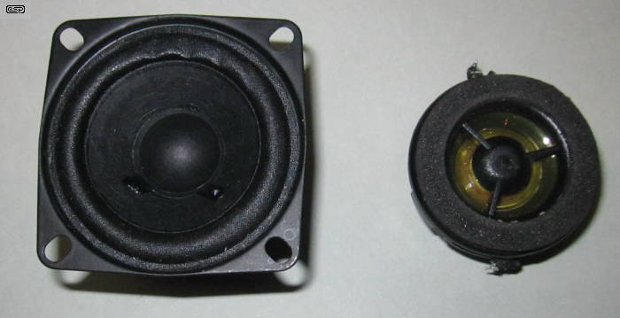
Figure 9 - Small 'Woofer' & Car Auxiliary Tweeter Used For Testing
The tweeter that I used for all tests (other than specific driver and enclosure testing) is shown above. It has a nice padded surround that's ideal for microphone tests, and it's small enough (35mm diameter) to fit into the type of enclosure that you'd expect to use for a project such as this. However, it doesn't have any mounting flanges, so some tricky brackets and/ or some glue will be needed to mount it to the front panel. Ideally, the padded ring would project outside the case, so a mic is easily pressed against it for a 'nice' fit.
The small 'woofer' is 50mm diameter and is actually a far better speaker for the task, but I only located it amongst my cache of speakers as I was finishing off this article. Interestingly, the speaker terminals were marked with the wrong polarity! The tester picked up this instantly. The range is quite good - I could detect the polarity reliably from up to 75mm from the cone with the microphone connection shown in Figure 3 (no additional amplification).
Bear in mind that if you use a small tweeter like the one shown above, it shows cone break-up at about 5kHz (200µs for a complete cycle). The first negative signal is larger than the initial positive signal (see Figure 6 - not the same tweeter, but very similar response). If the microphone is placed at around 70mm from the tweeter, the tester won't pick up the positive pulse, but it will pick up the first negative pulse. That means the polarity is shown as being the opposite of reality. I tested and verified this, and it's obviously essential to keep the mic very close to any tweeter to prevent a false reading. For this reason, a small speaker with a lower resonance (and greater resistance to cone break-up) would be preferable as the internal speaker if you can find one of the right size.
The tester can also be used to ensure that guitar pickups are wired with the correct phase. This is something that's generally assumed to be correct, but it may not be, especially with pickups from different manufacturers. Because plucking a string is an almost random process, you'll need to use the tip of a screwdriver or a small piece of mild steel to (gently) tap the top of the pickup.
The level will be quite low, so you'll almost certainly need the Figure 4 mic preamp to ensure the level is high enough to be detected. This will depend on the pickup itself, and some may not require any additional amplification. While it's likely that pickups will be normally connected in-phase, you may well find that out-of-phase gives better results. This is particularly true for 'neck' and 'bridge' pickups, because they detect vibrations at different positions of the strings.
The design has many options so that you can test speakers, leads, microphones or complete systems. You can add additional connectors if required to make the system as flexible as you need it to be for your application. Anything not needed is simply left out. It's been designed to be as flexible as possible, yet not so complex that a competent person can't wire it all together on Veroboard or similar. Each part of the circuit has been simulated, as well as built and tested, so I know that it all works as described ... provided no errors are made during assembly.
This isn't something you'll need or use very often (in most systems), but it's the quickest way to check that your microphone(s) and ancillary equipment are wired properly. Because it's a project that may only be used a couple of times a year (unless you are building speaker systems or are responsible for maintaining a number of mics), it may be easier to use an external power supply rather than the in-built 9V battery. The great disadvantage of batteries is that if left in equipment, they will leak eventually. This isn't an issue if you religiously remove batteries from equipment that's not in use, but many of us aren't quite so well disciplined, and having to repair gear that's been attacked by battery fluid is a pain, and best avoided.
Of course, both options can be included - battery and external power (anything from 9V to 12V DC is fine). This allows the best of both worlds, so mains power can be used in the lab or at home, and battery power can be used 'on the road'. The total current drain is modest, and it will draw an average current of no more than 5mA in use. You might expect somewhat more, but the pulse delivered to the speaker is very narrow (less than 1ms), and although the pulse current is fairly high at up to 1A, the low repetition rate and narrow pulse keeps the average current low.
This project isn't one that I expect to be particularly popular, although it is very good for verifying the polarity of loudspeakers (especially tweeters). The results of using it with multi-way speakers including a crossover network are less certain, and this is something I leave to the constructor, as I didn't verify it (my speaker system is triamped, so it's irrelevant to this topic). I did test it with a 2-way system in my workshop and got consistent results. Bear in mind that large, relatively inefficient speaker drivers may not respond to the narrow pulse quickly enough to produce a usable signal, but they should still work if the internal mic is close enough to the cone (probably no more than 10mm or so). I don't have one available to test this though.
If you'd like a file that can be used instead of one or the other pulse generator circuits, This WAV File can be downloaded and recorded. It's a sequence of positive pulses (actually a single polarity sawtooth waveform), and it can be saved to a memory stick or recorded onto a CD. The file is only short (about 9 seconds), and would normally be set to repeat. If you have a sound file editor, you can duplicate it so it's as long as you need (I limited the length to keep the size to something sensible - a bit under 2MB).
| Main Index
Projects Index
|