
|
|
| Elliott Sound Products | Project 181 |
Measuring vibration is an important undertaking in many fields, because it can cause great damage. Earthquake vibration is probably one of the most destructive force in nature, and the sensor of choice is a seismometer. These are large and expensive because they react to very low frequencies and usually have very high sensitivity. For most of the things hobbyists need to do, high sensitivity and very low frequency performance aren't necessary. The arrangements shown here are ideal for most common measurements, being relatively low cost and easy to implement.
Science and engineering need accelerometers for countless different applications. In audio, one of the areas where it's handy is when building a speaker box. Panel resonances can sometimes cause a panel to radiate at almost the same level that the speaker is producing, causing sound colouration that may be highly objectionable. The general principles described here aren't limited to loudspeaker boxes though - any form of vibration can be measured, and I once embarked on a project that used an accelerometer to monitor a heartbeat. The project was never completed (it was for a client who ran out of money), but the accelerometer approach worked very well indeed.
Panel vibration is one of the great unknowns when building a loudspeaker system. You pretty much know that if you can feel a panel vibrating, that's probably bad, but how bad? How does one decide if an attempt at suppressing vibration has been a success? Our sense of touch is very good, but it's hardly calibrated, and if we do manage to reduce the vibration (or shift its frequency), a 'finger-tip' probe is unlikely to tell us what we want to know. Likewise if we are trying to analyse (and then hopefully reduce) vibration from a machine.
You might imagine (at least initially) that since 'traditional' musical instruments rely on resonances to create their sound, that allowing a speaker to do the same would perhaps be more 'musical'. For example, if you placed a speaker in the sound hole of an acoustic guitar, that might make (some) recorded acoustic guitars sound 'better'. Everything else would also try to sound like the guitar body in which you mounted the speaker, and that most certainly will not improve matters at all. The difference is that a guitar (or any other instrument) produces sound, and it's the job of a loudspeaker to reproduce each and every instrument (including vocals of course) to sound as close to the original as possible. This is impossible if the speaker cabinet has its own 'sound', because that becomes superimposed on everything it attempts to reproduce. This is why most designers try very hard to make cabinets as 'dead' (non-resonant) as possible.
While I do spend quite a bit of time in this article discussing loudspeaker cabinets, accelerometers are useful tools for a whole range of disciplines. This website is largely about audio, so it's natural enough that audio applications would be my first suggestion. With appropriate modifications to make the accelerometer probe suited to other applications, the principles can be used nearly anywhere. While only one axis is generally needed for determining panel resonances, many of the MEMS (micro-electro-mechanical systems) ICs are 3-axis devices so can be used in true '3D' applications.
Accelerometers are available in a wide range of different types, styles and sensitivities, but there are several that are suitable for measuring cabinet panel resonance Unfortunately, most of the MEMS accelerometers might seem ideal, but they have a limited upper frequency. I don't know what the upper limit might be, but from my own tests and (possibly apocryphal) tales found elsewhere, you probably need to be able to measure up to 1 to 1.5kHz. In an enclosure with good internal damping (acoustic 'fill' such as fibreglass or polyester 'wool'), you probably won't get too much movement above 1kHz, but that depends on the material used for the enclosure.
Many of the MEMS accelerometers are limited to around 400Hz, and that's too low to be very useful for panel measurements. This is a shame, because they are cheap and readily available, whereas devices that can measure a wider frequency range are comparatively expensive and a great deal harder to get. Many piezo accelerometers are suitable, but they are not inexpensive (typically in excess of AU$100, some quite a bit more). Depending on where you get it from, the Measurement Specialties ACH-01 can be a snip at not much over $75 (but it is often a great deal more). Another that looks ideal at first is the Minisense 100, but its resonant frequency is far too low (75Hz) and its extremely low capacitance (244pF) means that a very high impedance amplifier/ buffer is necessary. The last two are shown below for reference. Neither is considered here, as the ACH-01 is relatively expensive (and I don't need one), and the Minisense 100 is unsuitable because of its low resonance and very limited high frequency response.
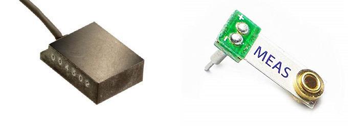
Figure 1 - ACH-01 And Minisense 100 Accelerometers (Not to Scale)
The accelerometer output should ideally be analogue. That makes it easy to measure the output with an AC voltmeter, or (and preferably) viewed on an oscilloscope. While the same can be done with a digital output, it's far more irksome. A digital signal requires digital processing and a DAC (digital-to-analogue converter) that only makes the system more complex, far more expensive, and much more difficult to understand. It should come as no surprise that the vast majority of accelerometer projects on the Net are based on an Arduino or similar micro-controller.
For reasons that I find obscure, it's now common to use a microcontroller where the job can be done just as (or more) easily with a dual opamp. Given that the ESP site is dedicated to analogue electronics, it's no surprise that I consider the use of a micro for everything to be counter-productive. This is evident here, where the accelerometer's output will typically be read using an oscilloscope (PC based is fine) or with speaker test software, where the accelerometer is used in place of the microphone. For the latter, you may need to include a pot at the output of the circuit to reduce the level to something the test system can accommodate.
It's worth reading this article in conjunction with Loudspeaker Enclosure Design Guidelines, which explains in general terms the causes and remedies available for enclosure panel resonances. Designing an enclosure to be a rigid as possible is difficult, but if you can identify problem areas with an accelerometer, it can help to ensure than any changes you make actually work. It's all to easy to imagine that a change has achieved something useful, and if you can't measure the difference you can be fairly sure that the change didn't help.
As noted above, panel resonance is something that few constructors can test. Without an accelerometer, you have no idea of the magnitude of the panel vibrations. Any panel can vibrate, but larger and thinner panels will obviously be worse than small, thick panels or part-panels. Any panel can be divided into separate sub-sections with bracing, but that may not be sufficient to reduce the sound output from the panel itself from being intrusive [ 2 ]. An accelerometer lets you determine if an attempt at reducing resonance has worked or not.
The second reference (indicated above) is a very detailed study that examined a great many different techniques and materials, and is recommended reading for anyone who wants to look at ways to reduce panel vibrations to the minimum. It's a fairly long document with many graphs of measured results, but the final outcome is that MDF (medium density fibreboard) remains one of the better materials for speaker enclosures. This is despite claims that you should only use 'special' timbers in ply combinations that may be expensive or unobtainable where you live.
MEMS accelerometer ICs respond to DC (so can measure the earth's gravity), but this isn't necessary for audio. Piezo accelerometers all have a low frequency limit, and it's generally far lower than anything needed for audio. Sensitivity varies widely, but there's probably no real need to calibrate the system because it's impossible to know in advance how many gs (units of gravity) will cause problems. The main thing is to get a signal level that's easy to see and/or analyse.
If you have some basic speaker testing software, you'll be able to use the accelerometer instead of the microphone. This will let you look at the signal picked up from the speaker box panels, and it shouldn't take long before you get a feeling for what is potentially audible and what is not. Depending on the software you have, a waterfall plot can show persistent resonance effects. This will be much more revealing than the rather subjective 'test' of rapping on the panels with your knuckles.
In general, we'd like panel vibrations to be well damped so they dissipate energy quickly. The amplitude should be as low as possible, but only within reason. Making speaker cabinets from 100mm thick reinforced concrete might seem like a good idea to eliminate vibrations, but you might just find that it's worse than well braced MDF (medium density fibreboard), and far harder to reduce with damping materials. Elimination of panel resonance is simply not possible, but minimisation is usually possible if you can take 'before and after' measurements.
Damping material is worth using. It should be dense, acoustically dead, and compatible with common adhesives. The optimum wall configuration is the subject of much debate, many patents, and no small amount of snake oil. Note that the latter is unlikely to provide any benefit  . The same thing applies to 'special' varnishes - the density of almost all protective finishes is far too low to have any measurable effect unless many coats are applied. Claimed 'magic' properties are just claims, and should be ignored.
Am I going to suggest 'optimum' box construction techniques? In a word, "no". There are so many variations and so much debate that I'll leave this well alone, but by using an accelerometer, you can make decisions based on real-world tests on materials of your choosing. These are a few points that I can make though, and these are fairly well known to many speaker box builders.
In practice, we need to ensure that panel resonances are benign, or as benign as we can make them. While elimination is a worthy goal, it's impractical and is verging on being impossible. The energy from the rear of the cone can't simply disappear, and it has to be dissipated in some lossy material. This is easy enough at upper midrange frequencies by using a suitable speaker box stuffing material (polyester fill, fibreglass insulation 'bats', long strand natural wool or your preferred material. These materials are not equal, but I won't go into details here.
Internal box resonance is also an issue, and all bracing should be asymmetrical. This simply means that each braced section should be a different size from any other. This ensures that no two panel sections will have the same resonant frequency, thus spreading the energy over a wider range. If each resonant panel acts on a different frequency the effects are distributed, and if done properly each will have a lower peak amplitude. In an ideal world, all panels would be a different shape and size, but such an enclosure is extremely difficult to design and fabricate. Having said that, some amateurs with poor carpentry skills may just produce the optimum enclosure by accident (unlikely I suspect).
Acceleration due to gravity is 9.8 m/s² (roughly 32ft/s²). This isn't particularly helpful in the context here, but it does set the base line.
I have an accelerometer that I built many years ago. It uses an Analog Devices ADXL150 MEMS chip (SMD), which has an output of 38mV/g. Maximum input is ±50g I used an amplifier with a gain of either 2.63 (100mV/g) or 26.32 (1V/g), and calibrated the setup using the earth's gravity. There's an offset control so the output can be zeroed, but if only used for speaker box testing the output can be capacitively coupled. Using DC coupling does allow one to check calibration at any time, simply by pointing the probe straight down (+1g) or straight up (-1g). This IC is no longer available, so you'll have to use something else (as described below).
When you first start playing around with an accelerometer, you'll find that panels, bench tops and other surfaces move further and faster than you may have ever thought It's quite easy to get a reading of 5g or more just by pressing the accelerometer against a surface, and tapping the same surface with your fingers. Even things you thought would be quite rigid can have considerable movement.
A sensitivity of 100mV/g is probably about right for many tests at a reasonable power level. Assuming that the signal will be digitised in many cases (e.g. for frequency analysis), that means you have a range of about ±20g. Adding a gain of 10 (1V/g) means that you can use less power, but noise will be greater. If a MEMS IC is used, the DC component (the earth's gravity) is a nuisance, and AC coupling should be used. However, the earth's gravity can also be used to check calibration which is handy.
The choice of the actual device isn't easy. You have to decide just how much you are willing to spend, and accelerometers costing over AU$1k are common, especially for those intended for industrial and scientific applications. Most cost less, but many piezo types are around $150+ with MEMS ICs available for less than $10. A small sample is shown below, along with their current 'life status' (the last two are devices I have, but are no longer available). Like so many devices these days, the accelerometers listed may have rather short life-cycles, and may be obsolete in a few years (or less).
| Model | Sensitivity, mV/g | Frequency | Vcc |
| ACH-01 ¹ | 9 | 2 - 20k | 3 - 40V |
| 805-M1-0020 ¹ | 100 | 1 - 8k | 5V |
| MMA2204KEG ² | 300 | DC - 400 | 5V |
| MMA2241KEG ² | 200 | DC - 400 | 5V |
| ADXL103 | 1,000 | DC - 500 | 5V |
| ADXL2293 | 312 | DC - 500 | 5V |
| LIS332AR | 600 | DC - 220 | 3V |
| ADXL335 | 300 | DC - 1.6k | 3V |
| ADXL150 ³ | 38 | DC - 1k | 5V |
| TR3BPN ¹ ³ | 1,000 | 0.3 - 8k | 5V |
1 Piezo with in-built amplifier
2 At 'end of life'
3 Obsolete (but devices that I already have)
Piezo devices (such as the TR3BxN) are very good, but rather expensive these days. The unit I have is now obsolete, but similar accelerometers are still available. For example, TE Connectivity (formerly Measurement Specialties) makes a range of piezo accelerometers with in-built charge amplifiers, but at around $150 (at the time of writing) it's not a option that most will pursue. The 801-M1 series is pretty much ideal, and it may be possible to get one for under $100 if you look around. The ACH-01 types just use a JFET buffer, but the expensive types use a circuit called a charge amplifier. It's rather outside the scope of this project to go into details, but there's plenty of info on-line. Suffice to say that charge amplifiers aren't trivial, despite the simple-looking circuit.
Of the MEMS types, the ADXL335 is probably the most suitable. It's available ready-mounted on a small PCB, and is intended as an Arduino (etc.) add-on. It is a 3-axis type, but for the intended purpose we only need one axis (X). The axes are marked on the PCB itself, and the entire setup should cost no more than around $5. The board does need to be modified to get the full bandwidth available from the IC. The leads also need to be kept fairly short (and/ or shielded) because it has a relatively high output impedance of ~32k. With an output of 300mV/g it's not perfect (100mV/g would be better), but it's one of the few that's truly affordable and no-one will fret too much if something happens to it.
There are various other sensors that are often referred to as 'vibration sensors'. Most of these simply detect if vibration exists above a preset threshold, and they are not accelerometers. There are other true accelerometers as well, but may not be suited to DIY activities. Some are very expensive, others are not only expensive, but require complex electronics. For anyone who simply wants to be able to detect and measure vibration in a panel or machine, I suggest that you start with a simple (and cheap) option first. You can move to something more capable if necessary later on, after you've mastered the basics.
Accelerometers are used in cars to sense a collision and trigger the airbags (hopefully not Takata), in robotics (including 'battle bots'), pedometers and other 'activity monitors', mobile phones and tablets. They sense the orientation of the device, and can even be used as inclinometers (essentially a digital spirit level) to show the angle (or tilt) of the device. These can be surprisingly accurate, and are able to measure an incline to within 0.1 of a degree. They are also used in washing machines to sense an unbalanced load, and of course are useful in many industrial applications where machine vibration needs to be monitored in real time. For amateur uses, analogue is preferred because you can look at the output on an oscilloscope, or send it to a PC's sound card for further processing.
Processing includes FFT (fast Fourier transform) to extract the amplitudes and frequencies involved in the vibration, and 'waterfall' plots (aka CSD or cumulative spectral decay) can show the persistence of a resonance after an impulse. This is an indicator of the Q of a resonance, and high Q is fundamentally bad for a speaker box panel because it shows that the panel continues to 'ring' after an impulse. The ideal is for the vibration to stop instantly, but this doesn't happen in our universe.
Digital accelerometers are still analogue! The only difference is that they have an internal ADC and output a digital data stream that can be read by a microcontroller. For most purposes for hobbyists and general purpose measurement they are far more difficult to use than analogue types. If you have to add a microcontroller (such as Arduino or Raspberry Pi), then the micro has to be programmed and the output sent to an LCD screen (for example), making the device less useful than a simpler analogue solution.
If you wanted to, you can use an accelerometer to provide feedback from a subwoofer. This lets your system monitor cone movement compared to input signal, and make corrections where needed so that you can potentially reduce distortion and extend bandwidth. There are a few subs available that do just this, but there's not much evidence that the extra complication provides any tangible benefit other than 'bragging rights'. The earliest implementations were often referred to as 'motional feedback', and you'll still see that term used. In reality, the added complexity almost certainly isn't worth the (usually) modest improvements. Ultimately, room effects will always dominate low bass frequencies, but panel vibration can also contribute if the box is not of adequate stiffness.
Looking on the Net will show hundreds of different applications, and some are very ingenious, albeit somewhat frivolous in a few cases. Most of these 'frivolous' applications would have been prohibitively expensive even 20 years ago, when accelerometers were very serious pieces of scientific kit. Now that we can go out and buy one for under $5.00 there's no good reason to not use one whenever you think it might tell you something new or interesting. Just be aware that you may not like what you see!
An interesting experiment is to use the accelerometer on a timber floor (concrete on the ground doesn't work well), then see if you can walk around without it detecting the vibrations. I don't know if it's done very often, but it makes a rather good intruder detector, because it's almost impossible to move about without creating some vibration. Forget it if you have pets, because they will almost certainly set it off when you are away from home!
There are a great many possibilities here, but I can show you an example of my early accelerometer. This was made many years ago, and it works very well. Having the DC output is a nuisance, and while it does let me measure gravity, I can't think of a good reason to do so. I've not noticed any changes where I live, and you won't either. However, it does provide a convenient means of calibration if you think that's important. For the purposes described here, we really don't care about calibration at all, since most measurements will be relative.
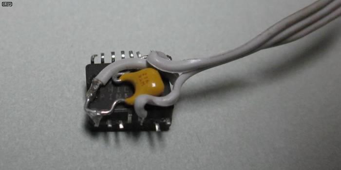
Figure 2 - ADXL150 Accelerometer With Wiring
The above shows how a standard SMD IC can be terminated. It's rather fiddly, but this works very well. The ADXL150 was originally protected by heatshrink tube and hot-melt adhesive, but that was removed so I could take the photo. The final assembly is reasonably robust once everything is protected and held in place by adhesive. An even better solution would be epoxy encapsulation. Unfortunately, doing that means that if a wire breaks the unit is defunct, so I chose the 'soft' option. This is especially important because the IC is no longer available, which is a shame because it's perfectly suited to the task.
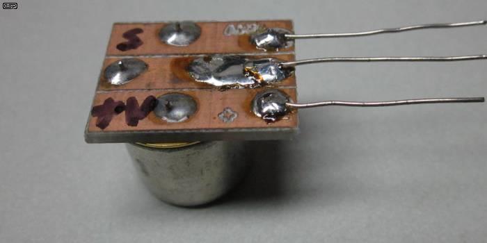
Figure 3 - TR3BXN Accelerometer With Terminal Board
The TR3BPN (the 'positive output with pins facing up' option) that I have is a large metal encapsulated (TO-8) device with three pins. The terminal board is marked to show which is which. This device uses a charge amplifier as the impedance converter, and like all charge amps it takes some time before the output settles to the quiescent 2.5V. The datasheet claims 15 seconds, but it's actually closer to 1½ minutes. This isn't a major problem, but it does mean that you can't just 'switch on and go'. Like the ADXL150 shown above, this accelerometer is also obsolete. Similar devices are available, but they are expensive.
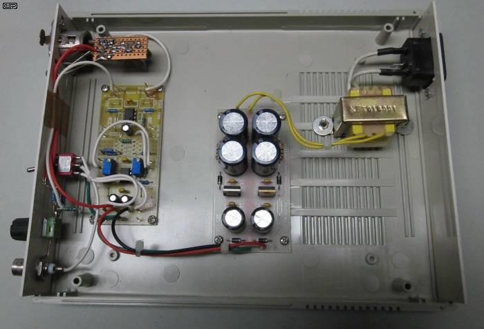
Figure 4 - Accelerometer Preamp Internal Wiring
The internal wiring of my early accelerometer preamp is shown above. It uses old versions of P88 and P05, with a small 5V regulator IC mounted to the Veroboard attached to the XLR input connector. The P88 preamp board was used because I have them handy - almost anything can be used, including Veroboard for everything. Mine is mains powered, but you can also use a 9V battery or an external 12V supply if preferred. An equivalent circuit is shown further below - it's not the same as that I used at the time, because that was simply adapted from a test build of the P88 preamp I'd been playing with. One dual opamp is all that's needed.
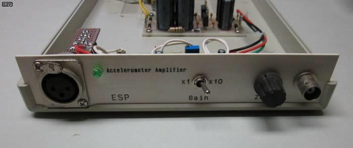
Figure 5 - Accelerometer Preamp Front Panel
This is the front panel. You don't have to use an XLR connector of course, and any suitable 3-pin connector will be fine. Ideally, it will be set up so that incompatible devices (such as microphones) can't be plugged into the accelerometer preamp, but in reality that's unlikely unless you have unskilled people milling around in your workshop. I used a BNC connector for the output because that's what is used on all my test gear, but you should use a connector that suits your setup. Provision of alternate gain ranges is optional, and although it doesn't affect the range of the accelerometer you use, it does let you get the best signal to noise from the connected monitor (oscilloscope, PC interface, etc.). The zero control pot isn't necessary if you AC couple the signal, and it hasn't been included in the 'signal conditioner' circuit shown below.
One thing that is immediately apparent with the one shown above is that I 'over-thought' the whole process, and made it far more complex than was necessary. Pretty much as a direct result, it never got a great deal of use because it was a pain to set up, and DC coupling made that even worse. While the SMD chip alone seemed like a good idea at the time, it really does need something with a flat base so that orientation is not critical. Even a small angle from the vertical (to the panel, not in absolute terms) changes the output, and this ultimately made it hard to get good relative (before and after) measurements.
The suggested device is the ADXL335, which comes in a 4mm × 4mm × 1.45mm, 16-lead, plastic 'lead frame chip scale package' (LFCSP), which is a very small leadless encapsulation. This makes it much harder to adapt than even more 'traditional' SMD packages. The PCB shown below has capacitors that limit the HF response rather drastically, so when you've selected you preferred axis (either 'X' or 'Y') I suggest that the capacitor be removed. You may expect a large noise increase, but this isn't the case. Response extends to 1.6kHz which should be quite sufficient for all normal testing.
The ADXL335 is shown on its little PCB, which includes a low dropout (LDO) regulator to provide the 3V supply for the accelerometer. You can see that one of the output filtering caps has been removed ('X' axis) to obtain the maximum frequency response. You can use either the 'X' or 'Y' axis, but the 'Z' axis is less useful as it has a maximum frequency response of 500Hz, even without the external cap. The output impedance of each axis is around 32kΩ, higher than optimum, but we have to live with it.
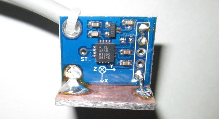
Figure 6 - ADXL335 Accelerometer With Standard PCB, Cable & Mounting 'Foot'
Note that the maximum range of the ADXL335 is not that great, at ±3.6g. This is set by the sensitivity (300mV/g) and the supply voltage (3V). This allows a total output of ±1.08V because the IC's output stage can't get to zero or 3V. The datasheet indicates that the actual sensitivity can vary from 270mV/g up to 330mV/g, with a 'typical' figure of 300mV/g. Mine measures 307mV/g (taken as a DC voltage directly from the PCB).
The mounting foot lets you attach the PCB to the side of a speaker box using double-sided tape or something similar. The adhesive should not be a 'permanent' type, as that will make it difficult to remove the accelerometer without damaging the speaker box finish. You will find that it's easy enough to just hold the board in position, and the foot means that you don't need to worry about keeping the PCB at a perfect right-angle to the surface.
Figure 7 - ADXL335 Accelerometer Board Schematic
The drawing shows the circuit of the ADXL335 board. There's very little to it as you can see from the above and from Figure 4. It doesn't matter if you use the 'X' or 'Y' axis for the output, so pick the one that suits the way you want to use the PCB. You can use both, but there's not really any point, and you then need switching at the PCB or a 4-way cable. As noted, the capacitor 'Cx' should be removed. It's not disclosed anywhere, but these are probably 10nF caps by default, which gives a cutoff frequency of 500Hz. If you do decide to use Cx, then 2.2nF is suitable, but it's easier to leave it off. The output pin of the accelerometer IC has an impedance of around 32k because of the internal resistor. This makes it sensitive to noise, so the lead must be shielded. A light duty 2-core shielded cable should be used to prevent the cable's mass from affecting readings.
I've shown the 1458 opamp as an alternative because it is characterised to operate from as low as a single 5V supply, compared to a minimum of around 10V (±5V) for the TL072, so the circuit can be run from a 9V battery. If you use an external 12V supply, the TL072 is a better choice because it's somewhat quieter. Both are inexpensive opamps but their performance is more than satisfactory for the purpose. The ADXL335 has an output of 300mV/g, and this is slightly greater than the final sensitivity of the unit. It may be a little inconvenient (it's not a nice, round number like 1V/g for example), but adding more gain would only ensure that most mic input circuits would be overloaded. D1 is optional (it protects against reversed polarity), and it can be a Schottky diode if you think you need a low forward voltage.
Note that there is no provision to measure gravity because the circuit is capacitively coupled. To allow for gravity measurement, the circuit would need a dual supply with direct coupled amplification throughout. You can test the sensitivity of your accelerometer by measuring the output voltage with a multimeter. Measure the voltage between TP1 and TP2 with the 'X' axis pointing directly to the ground, then adjust the position carefully until you get a minimum reading. Then, invert the accelerometer board and measure the maximum voltage. The peak sensitivity is half the difference between the two readings. For example, if you measure (say) 2.3V minimum and 2.8V maximum, the sensitivity is exactly ±( 2.8 - 2.2 ) / 2 = 300mV. The easiest way to get maximum and minimum readings is to place the accelerometer board on top of then underneath a level table or workbench.
When subjected to this test, my unit gave readings of 1.3220V and 1.9884V, so its sensitivity is 333.2mV/g. AC response is 322.9mV/g calculated as shown below, due to the voltage divider created by the IC's output resistance and the 1MΩ bias resistor (R1) for AC.
The 5V supply is used to bias U1A, which also biases U1B because they are coupled via the 3.9k resistors. It doesn't matter if it's a bit off, because the supply voltage is more than enough to ensure that the accelerometer output will clip at the ADXL335's output first. Adding more gain is not particularly useful for testing speaker boxes. Note that the 1MΩ resistor (R1) creates a voltage divider with the ADXL35's output resistance, and that reduces the sensitivity to about 290mV/g. This makes it a bit harder to work out the actual g-force exerted, but it's not very useful anyway so I made no attempt to correct for it. If you use a 4558 dual opamp, replace R1 with a 220k resistor. This increases the attenuation of the accelerometer's output (about 260mV/g, assuming that the ADXL335 really has an output of 300mV/g). Sensitivity can be from 270mV/g to 330mV/g according to the datasheet.
Figure 8 - ADXL335 Signal Conditioner With Filter
The filter circuit reduces noise, and it's set for a cutoff frequency of 2.8kHz, slightly above the 1.6kHz (claimed) upper frequency for the accelerometer. With the values given, the response is within 0.5dB up to 2kHz to ensure that readings aren't affected (the level is +0.18dB at 1.6kHz). For speaker box vibration tests this is a good option, and it doesn't limit the uses for the accelerometer. Although you could use a sharper filter (e.g. 24dB/octave) there's really no point.
If a 1nF capacitor is used at the output of the accelerometer PCB, the filter becomes 3rd order (18dB/octave) with a -3dB frequency of 2.56kHz. At 1.6kHz, the output is less than 0.3dB down. While the 18dB/octave filter will reduce noise a little more than the 12dB filter shown, the difference in real terms is negligible. With no filter at all the noise level is rather intrusive. I measured about 3.2mV RMS at the output of the accelerometer (around 45dB signal to noise ratio). This is a measurement system, and you don't have to listen to the output (although doing so may be quite revealing).
The power supply you use is not critical, although a switchmode wall supply may increase the overall noise level. If possible, use an old linear supply, as it will be comparatively silent, or you can build a supply using a 9V transformer, 4 diodes and a fairly large filter cap to maintain low ripple. The circuit doesn't draw more than around 10mA, and it doesn't need to be regulated, although including a regulator will reduce noise. If you use a regulator, a 7812 (or 78L12) is fine, and the transformer should have a 12-15V secondary winding.
Figure 9 - Unregulated And Regulated Supply Options
The unregulated version will have a ripple of around 10mV peak-to-peak (3.5mV RMS) with a 10mA load, which is unlikely to cause any issues. For very little extra trouble, the regulated version ensures ripple will be well below 1mV P-P, and the added cost is minimal. Ripple can be reduced for the unregulated version by increasing the capacitors to 2,200µF cap, retaining the 10 ohm resistor separating the two. The output is taken from the second cap. This will give better ripple performance that's still not as good as the regulated version, and it will probably cost more (unless you have the parts already).
While I have suggested against a switchmode supply, Figures 14 and 15 were captured using one, and noise appears to be quite acceptable. Feel free to use a switchmode supply, but be prepared to add some extra filtering to remove high frequency noise. While the noise won't be audible, it will still show up on the scope trace. This makes the readings taken harder to see clearly.
The section above describes many of the issues faced, and in the interests of completeness I also ran some tests. I don't have the time or the patience to try to duplicate the extensive testing done by others, but I ran tests on a speaker box that I had to hand that show clearly the sort of results you might obtain from simple enclosures that appear very solid, but show distinct resonance effects at a number of frequencies. The vibration levels shown are not referenced to the speaker output, but are 'stand-alone' measurements. You will likely find it difficult to get separate SPL readings for the speaker and panel(s) unless you have a very sophisticated test setup. The filter circuit hadn't been built when I took these measurements, so I used the low-pass filter facility in my oscilloscope.
You don't need to use high input power (in fact that's a bad idea for many reasons). 460mV doesn't sound like much, but you don't need more than the ~26mW I used, and more than 100mW just means that the noise level while taking measurements becomes really annoying. The panels will resonate at any power level, and high power means that you run the risk of overloading the accelerometer. The only time a higher power is needed is if you have to track down a rattle or other gross disturbance caused by poor panel fit or something loose within the enclosure.
I captured the panel resonance of a sample speaker box using the ADXL335 accelerometer, with the speaker driven with a tone-burst at the frequency where resonance was most pronounced (in this particular case, 310Hz). The tone burst allows you to see the attack and decay characteristic of the panel's vibration. The image below is a capture from my oscilloscope, and the decay is clearly evident. While it's not a particularly pretty sight, the box in question actually doesn't sound too bad. There's certainly little evidence of severe colouration, despite the magnitude and decay characteristic of the panels.
Input was directly from the function generator, which has an output impedance of 50 ohms. That's shown in the blue trace on both captures below, and is at a level of 650mV peak (460mV RMS). You can see the speaker's back EMF when the signal stops - there are a few cycles at the speaker's resonance (about 90Hz). There is some noise evident on the accelerometer trace (yellow), but it's not too bad because I used the filter option in the oscilloscope rather than the filter described. The filter circuit shown in Figure 8 is much easier to use than a digital oscilloscope's filter (which changes frequency by itself if you change the timebase). This does mean that the level is a little higher than you'll measure with the filter circuit, because the oscilloscope has minimal loading on the output signal.

Figure 10 - Side Panel Resonance
The first thing you notice is that the output of the accelerometer (yellow trace) takes some time to build up to the maximum, and takes (roughly) the same amount of time to decay again. This indicates a fairly high Q resonance. The blue trace is the input to the speaker, taken directly from my function generator, set for a tone burst output at 310Hz (the frequency display in the bottom right corner is wrong). Another giveaway that the resonance is high Q is the frequency range. At 290Hz or 320Hz the level drops to a tiny fraction of that measured. Given that the signal amplitude is roughly 28mV peak, that equates to an acceleration of ±0.093g.
Figure 11 - Baffle Resonance
The traces above show the output with the accelerometer placed on the baffle, right next to the woofer. The overall pattern is unchanged, but the level is considerably higher. At 50mV peak, that works out to ±0.17g. This level is barely detectable by a fingertip test, demonstrating clearly that the accelerometer can detect vibration well below the level we can feel. Even a rather high level of vibration is undetectable by a finger test if the frequency is high enough.
Given that the frequency is the same for the side panel and the baffle, this indicates an internal resonance that is likely due to the cabinet's volume, rather than panels vibrating of their own accord. Of course, both possibilities exist, depending on the cabinet size. The box tested is a medium size bookshelf speaker, measuring 350mm high, 230mm deep and 200mm wide. It's a vented box with a 130mm (5") mid-woofer. All panels are 18mm plywood, and are very stiff.
When I did these tests, the accelerometer was simply held in place with my fingertips on the mounting foot. I tried pressing hard and lightly, but the output level barely changed, so in many cases you won't need to mount the unit to the box, and can move it around at will to find the maximum resonance output. Ultimately, the absolute 'g' value is unimportant, and it's only necessary to verify that any change made reduces the measured amplitude, and it doesn't have to be a tone-burst signal. I used the tone-burst so I could demonstrate the (relatively) slow build-up and decay of the resonance.
I did not include readings from other panels to save space here, and nor did I show several other resonances that were easily measurable. There is no doubt whatsoever that the measurements are useful, and it won't take anyone very long to work out how to take their own measurements, as the process is fairly quick. You can't change the frequency quickly though, because you will miss any high Q resonance quite easily. I did see something 'interesting' above 700Hz in the box I tested, and it's shown below.
Figure 12 - Side Panel Resonance At 880Hz
I had to increase the number of cycles in the tone-burst, because the resonance takes so long to build up and decay (around 50ms). The previous traces used 13 cycles, but I increased it to 80 cycles for this test. As you can see, it takes around 50ms for the level to reach close to the maximum, and another 50ms before it's decayed back to 'background' level. This is a very high Q resonance, but despite the amplitude, it can't be felt with one's fingertips as the frequency is too high. Some people may be able to feel it, but most will not (I certainly can't). It's also noteworthy that it didn't matter at all if I pressed as hard as I could or not when measuring the resonance - the reading was unaffected. This appears to indicate that adding mass-damping materials to the inside of the panel is unlikely to have a significant effect.
Figure 13 - Side Panel 'Knuckle Test' (Accelerometer Output Clipped)
Finally, I rapped my knuckles on the side of the enclosure and took a reading of that as a reference (since this is a common way to test without an accelerometer). We expect to hear a dull thud that indicates a 'dead' (non-resonant) surface, but this shows clearly that there is a considerable effect. This particular speaker box does not produce the dull thud we'd like, and the resonance is quite audible with this test. Fortunately for speaker builders everywhere, adding internal absorbent material such as fibreglass will absorb these higher frequencies quite well, reducing the audible colouration.
However, this does demonstrate that the 'knuckle test' is probably not a very useful way to test for panel resonance as a 'stand-alone' test. The accelerometer clipped at +2 and -1.5V, which means that the reading was well in excess of the ADXL335's ±3.6g measurement range. Fortunately for us, internal air pressure can't exert anything like the force per unit area that knuckles, screwdriver handles, or any other implement can produce. It is apparent from the oscilloscope trace that the frequency is the same as the 880Hz test (this was verified using the oscilloscope's cursors), but the test itself is not particularly meaningful.
I decided to test a couple of panels I found in my workshop. One was plywood and the other MDF. They are both roughly the same size and thickness, and I used a simple 'knuckle test' on each so I could see if there were any major differences. The results are shown below. For both tests, the accelerometer was around 50mm from the top middle of the panel, and I rapped the other side about 150mm below the accelerometer.
Figure 14 - MDF Panel 'Knuckle Test'
The peak measured was a negative spike that came close to clipping the accelerometer, with the following peaks measuring -1,500mV and +750mV. This translates to -4.6g and +2.3g, based on the 323mV/g calculated sensitivity of the accelerometer IC with the filter circuit described above. Clipping was (just) avoided because the accelerometer axis was at a right angle to gravity.

Figure 15 - Plywood Panel 'Knuckle Test'
The plywood panel shows larger maxima (which admittedly may have been due to the uncalibrated nature of the test) and a greater duration. Both positive and negative peaks caused slight clipping, and you can see that the vibrations are greater and remain so for longer. The low frequency visible to the right of the trace is due to the panel swinging after it was struck. The plywood panel is quite a bit lighter than the MDF.
This is not a scientific test by any stretch of the imagination, but it's still something that tells you that plywood will ring louder and longer than MDF. Whether this is a problem or not depends on the construction of the enclosure, the use and positioning of bracing and/ or internal damping materials, etc. I included this only because it's a demonstration that you can find out a lot about a material just by a simple test. Space precludes adding more detailed test results - only selected tests have been included.
The accelerometer is a tool that reveals things that you never realised were (or might be) potential problems. It's up to each user to decide if the measurements indicate that corrective action is necessary, but I'd certainly be concerned if I saw readings approaching 1g at any frequency, based on the 26mW input I used (the measured level must be adjusted for input power). With a more-or-less typical driver of around 90dB/W/m, 26mW gives an SPL (sound pressure level) of 74dB at one metre. Any louder becomes really annoying, really quickly.
Being able to move the accelerometer around means that you can test for resonances at any point on the panel(s). Even if you are able to detect a resonance, that doesn't necessarily mean that corrective action is necessary. Resonance is simply a fact of life, and it's virtually impossible to eliminate it completely. A sphere is probably the only shape that is strong enough to minimise resonance levels without the need for extensive bracing, but they are hard to make and don't suit most people's idea of what a speaker box should look like.
Using thin walls that are more easily damped is one approach, and that's been used for several BBC monitor speakers. Unfortunately, this means that bass frequencies will almost certainly cause the panels to flex sufficiently that they become auxiliary sound radiators, with unpredictable results on the sound of the system as a whole. If you choose that method, expect to use lots of bracing, which will promptly increase overall stiffness, possibly resulting in the same problems found with panels that are stiff to start with. Some constructors prefer plywood over MDF (medium density fibre-board), but MDF tends to be less resonant by nature. Perhaps it's the colouration imparted by plywood or the relative 'deadness' of MDF that appeals, and I make no judgements either way.
At the time of writing, I haven't been able to determine what level may become audible in its own right. Even a high Q resonance such as the 880Hz response shown above may not be audible with music, because it may take too long for it to build up to the point of becoming audible. Music is dynamic, and it's only a problem if notes are sustained for long enough to cause audible colouration. One thing that is certain - very stiff panels will have high Q resonance(s) that may be almost impossible to suppress. The only viable option is to use bracing to move the resonant frequencies to higher frequencies, where they are less likely to cause problems.
While any resonance can be explained by science, moving it out of harm's way remains something of an art. As noted earlier, braces should (usually) never simply divide a panel in half, as that creates two near identical sub-panels that may move the resonance to a higher frequency, but provide two radiating surfaces that have the potential to make matters worse. By using an accelerometer during the build phase, problem areas can be identified and dealt with (usually experimentally) before the cabinet is veneered or painted. This is preferable to waiting until the enclosure is complete, where changes may damage the finish.
Ultimately, it's up to the constructor to evaluate the system's response, and use the accelerometer as a guide to minimising panel resonance. It's entirely possible that some systems will sound good despite any panel activity, and equally some may not sound good when there is none (or very little and at low level). Speakers remain an area where the final arbiter of quality is almost purely subjective. Having flat response is all well and good, but it's not an absolute indicator that a speaker sounds decent. There are countless examples of DIY and commercial speakers that are not flat but sound good, and the converse can also apply.
The idea of this project was to produce a low cost and easy to build accelerometer. Although it's essentially uncalibrated, this is of no consequence for measuring panel vibrations or for any other application where you are interested in relative results. Take a measurement, try adding damping material and/ or stuffing, and check again. You know immediately whether the change has made a difference or not. Even if you were measuring vibration in a machine of some kind (to check for imbalance for example), the relative reading lets you know if you're on the right track.
After the bulk of this article had been completed, I built the filter and ran a couple of the tests again. Needless to say, I got the same figures, but the output with the filter is definitely cleaner than shown in the oscilloscope captures above. All-in-all, this is a very useful little project, and is far more suitable for speaker (and/or other) testing than my earlier unit, which is cumbersome and will almost certainly be 'retired', or I may just install the unit described here in the same case with a switch to select the one I want to use. I think I know which unit will be selected 99% of the time.
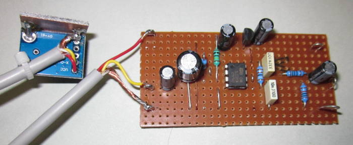
Figure 16 - Accelerometer And Filter Board
The above shows the (as yet not enclosed) filter board, with the accelerometer at the left. The two are joined by a 1 metre long 2-core shielded lead, which guards against noise pickup. As you can see from the Veroboard filter, there's not much involved, and you should be able to build it and start running tests in an afternoon. It will take longer to assemble a case and power supply, add input and output connectors and make a label so you know what it is after a few years, but it's well worth the effort if you are serious about building loudspeaker systems.
As noted earlier, there are a (small) few projects for speaker testing accelerometers on the Net, but nothing even close to as simple as the one described here. Despite its simplicity, it's a very capable vibration test unit, and I'm sure that there will be many amateur speaker-builders (and perhaps some professionals as well) who will recognise its value and simplicity. Given that the total cost (excluding power supply and fancy connectors) is under AU$10, it's very hard to beat in terms of value for money.
 Main Index
Projects Index
Main Index
Projects Index