
|
| Elliott Sound Products | Project 168 |
PCBs will be made available for this project, depending on demand
Before discussing the project itself, I need to mention that there are quite a few published circuits for low ohm meters, but some have not been well thought through. Despite claims by the author(s) that they work, even a cursory glance shows that they cannot possibly function as described. I'm not going to point out any that won't work, but at least one that I know of is highlighted as a 'feature' project. It's not at all helpful for anyone who tries to build the circuit, because they end up buying parts and putting a circuit together that's not going to be useful. When hobbyists build things, it's very disheartening when it doesn't work well (or at all), and they assume they must have made a mistake.
A low ohms meter isn't something that you'll need very often, and most readers will never need one. Capacitor ESR (equivalent series resistance) testers can be used to measure very low resistances, but only when there is virtually zero inductance in the circuit. This means that you can't accurately measure the resistance of the primary or secondary windings of a transformer because the inductance completely messes up the reading. You might get a reading, but it's completely wrong - it will be impossibly high. The same applies when measuring passive crossover inductors. They may only be a couple of milli-henries, but that will confuse an ESR meter rather badly.
All low ohm meters use DC, as this ensures that no amount of inductance will cause problems. There are many decisions to make though, and there are precautions that must be taken to ensure that you don't damage your meter or get an electric shock - very easy with inductive devices. The meter described is intended to be used with a digital multimeter, so it's an adaptor, and not a complete meter in its own right. You can add a digital panel meter if a self-contained instrument is preferred.
There are a few traps for the unwary when trying to measure very low resistances, and these are discussed below. In particular, dissimilar metals form little thermocouples that generate a voltage at normal temperatures, and this makes very low voltage readings unreliable. Added to that is contact resistance, which will be slightly different each time you attach leads to a component. Non-ohmic contact (due to contamination or corrosion) can even partially rectify RF (radio frequency) energy, perhaps adding up to a few microvolts or so of 'stray' voltage.
Please Note The Following:
The instrument described here is not an ESR meter, and cannot be used to test capacitors.
It is especially important to be aware that this meter is not intended for checking high current earth (ground) connections, busbars or any of the other tests that may be required to verify an industrial/ commercial electrical fit-out. It's common for professional testers to use 200A or more to verify the integrity of high current connections (whether bolted, rivetted, hard-soldered or a combination of these), with some tests requiring a great deal more. Such testers are generally expected to comply to various standards, and have current calibration certificates.
The tester described here is to allow you to measure low resistances in electronic applications, not electrical installations. There's a significant difference between the two applications, and it's not feasible to try to develop a tester to compete with the commercial versions that exist. They are seriously expensive, but are also intended specifically for testing electrical installations, where a failure may cause extensive damage and/ or loss of life.
Many digital panel meters and multimeters have what's called 3½ (or 4½) digit resolution. The 'half' digit can display either zero or one (0 or 1), so the maximum display will be 1999 or 19999 (with a decimal point as determined by the range selected). Somewhat more confusing are so-called 3¾ (or 4¾ etc.) digit meters.
The 3/4 digit isn't well defined, and it can mean that the meter can read 2999, 3999 or even 4999, depending on the whim of the manufacturer. This project can accommodate all meter resolutions equally well, but you will have to do some mental arithmetic to determine the resistance in all cases. If you use a digital panel meter after the differential amplifier stage, you may be able to arrange decimal point selection and full scale resolution with appropriate switching. This is not shown, because there are too many variations. You can also use an analogue (moving coil) meter with appropriate scaling resistors to suit the meter used. This option isn't shown either.
Many high-end multimeters have a 'relative' mode, which lets you effectively remove the resistance of your test leads. This is done by joining the leads, and pressing the button for relative mode. Whatever resistance was measured is now the new 'zero' reference. My bench meter has this facility, and while it's not entirely useless, it doesn't work as well as it might. The reason is simple - contact resistance. When a pair of test clips or probes are joined, the resistance of the connection is both unknown and usually unstable. Each time you join the test leads, you get a slightly different resistance. This is due to many factors, and the microscopic view will show that the surfaces are anything but smooth as they appear to the naked eye.
The variations are small - usually no more than a few milliohms, but if you need an accurate measurement of a 0.1 ohm resistor then the variation is typically as much as 10%, and worse with lower resistances. As much as you might try, it's pretty much impossible to get a reading that can really be trusted. A different technique is needed to get an accurate reading that is not affected by contact resistance.
The first thing to decide is just how much (or little) resistance you need to measure. Most multimeters will happily measure down to a few ohms easily, so the maximum resistance you need to measure will probably be no more than 10 ohms. The minimum depends on what types of things you want to measure. As the resistance is reduced, the necessary test current needs to be increased, or the voltage will be too low to measure accurately.
Measurements are taken by injecting a known current into the DUT (device under test) and measuring the voltage across it. Measurement current will generally be from a maximum of 1A down to 10mA or so, but low currents are not useful for low resistances. The unit described has test currents of 10mA, 100mA and 1A, and should be able to measure down to 10mΩ (0.01 ohm) accurately. Lower values can also be measured, but accuracy will be reduced due to thermal EMF generation (thermocouple effects) and measurement amplifier drift.
For example, with a test current of 100mA, you get a voltage of 100mV for a 1 ohm test resistor or 1 ohm of circuit resistance. If the resistance is less than 0.1 ohm, then you must either amplify the test voltage (10mV for 0.1 ohm) or increase the test current. If you don't, the resolution of the meter will not be good enough to provide an accurate measurement. The means of applying the test current and reading the voltage is important too. If you don't use what's known as a '4-wire' metering method, stray resistance in the measurement probes will cause large errors.
Figure 1 - 4-Wire Test Setup
The drawing above shows how to take a 4-wire (aka Kelvin) measurement. The test current is applied to the DUT (device under test), and the measurement is taken with a separate pair of wires, connected as close to the DUT as possible. They must be connected as shown above - literally. If this isn't done, your measurement will include the resistance of the current injection wires and the resistance of the connection to the DUT, which will often be highly variable. The connection resistance might be anywhere from 1 to 100mΩ, and this rather destroys the value of testing a circuit with perhaps 20mΩ resistance.
By separating the two connections, the connector resistance no longer matters. A current source will ensure the current through the DUT is maintained at the desired value, and the separate voltage probes measures the voltage across the DUT - the contact resistance is immaterial. If the meter (or amplifier) has an input impedance of 10k or more, then a few milliohms of contact resistance has a negligible effect on the measurement. Test leads don't have to be low resistance, and even 1 ohm or more will not affect the accuracy of the reading.
This type of measurement is very common in laboratory equipment, but is less common in service or hobby work because it can be a hassle to set up. Many multimeters allow you to set the zero reference so it includes the resistance of the test leads (often as a 'relative' measurement), but this can't compensate for imperfect contact to the leads of the DUT. Consequently, there is often a large uncertainty in the final measurement, and it will usually be slightly different every time you try to measure it. This is of little consequence if you only need to know that a connection exists, but it makes an accurate measurement impossible.
A low ohms meter is not required if you only need a rough idea of the resistance, and a resolution of 0.1 ohm might be fine for most service work. If you are designing something or doing experimental work where you need to get accurate readings, then it becomes a vital piece of test gear. Of course you can buy one - prices range from about AU$150 to well over AU$2,000 depending on the accuracy and facilities offered. All competent instruments will use the 4-wire measurement technique shown above.
In addition, some instruments have provision to measure the thermocouple voltage created when dissimilar metals are in contact, which is subtracted from the voltage measured when current is applied. With typical components and test clips, any such voltage will normally be very low, and while it is a source of error, this is unlikely to create a problem for the majority of measurements.
The voltage across the DUT has to be measured to get the resistance. Because the voltage may be as little as 10mV (e.g. 1A across a 10mΩ resistor) it has to be amplified or it's too low to obtain a decent reading with a multimeter. Some meters can measure down to 200mV, but not all are so sensitive. 2V is more common with typical meters, and that means that a reading of 10mV will generally have an uncertainty of ±1mV at best. This is a 10% error which is clearly unacceptable. The amplifier stage has to be stable with time and temperature, and must have minimal DC offset.
Despite it being a 'conceptual' circuit, that shown above is pretty much all you really need. The current source shows a simple zener, but it needs to be a precision voltage reference with a trimpot to allow the voltage to be set exactly. The 1 ohm resistor and reference voltage determine the test current. The meter shows a reading of 0.205V, which indicates a resistance of 20.5mΩ, so the DUT is 2.5% high. Reasonably accurate readings down to 10mΩ are possible with an 'ordinary' multimeter.
If you search for low ohm meter circuits, you may see the use of a Wheatstone bridge suggested, but that topology cannot do a 4-wire measurement, so contact resistance remains a major problem. It also means that you need a precision calibrated pot to get the null perfect, and they are (potentially very) expensive. A pot with the necessary accuracy could easily cost far more than the instrument described here. If you don't know what a Wheatstone bridge is, look it up.
The general specifications for the meter adaptor can now be determined, based on the principles described above. Ideally, we'd like to be able to use a multimeter or a digital panel meter. The latter are mostly 3 digit, but there are panel meters available up to 5 digits. You need to read the data carefully to find out what to expect. The most significant digit may count up to anything from 1 to 9, and it's not always obvious.
If you use a panel meter (as shown below), it must be a 3-wire or 4-wire type, having separate power and measurement connections. Not all do, and although a 3-wire meter is ok (supply, input and common), simple 2-wire meters are completely useless in this application. Some panel meters have provision to let you move the decimal point or are auto-ranging, but others do not. This may require a bit of mental arithmetic to get the final resistance value.
The general specifications are as follows, and accuracy should be better than ±2% if possible ...
| Current | 10 mA (Optional) | 100 mA (Preferred) | 1 A (Optional) |
| Rmin G = 10 | 100 mΩ | 10 mΩ | 1 mΩ |
| Rmin G = 100 | 10 mΩ | 1 mΩ | 100 µΩ |
| Vout (x 10) | 1 V @ 10 Ω | 1 V @ 1 Ω | 1 V @ 100 mΩ |
| Vout (x 100) | 1 V @ 1 Ω | 1 V @ 100 mΩ | 1 V @ 10 mΩ |
The table above shows the typical ranges we should be able to get, with the maximum resistance being dependent on the multimeter or panel meter used. The output voltage is nominally 1V with the maximum resistance, but this also depends on the meter used. The practical maximum output voltage is 2V if your meter goes to 1.999 (for example), and ideally the maximum output voltage from the amplifier will be no more than 4-5V, useful because some meters can read that as full scale. There is no point having ranges above 20 ohms because your multimeter can already do that quite easily.
You need to be careful using any low ohms meter, because a test current of 100mA or 1A might exceed the ratings of the device being tested. If your test causes failure, or heating to an extent that causes the thermal coefficient of resistance to inflate the measurement, then it's not very useful. This is common - some meters use a lower current and a higher gain amplifier, but that's not always practical - especially for a home build. Some specialised meters use a test current of 10A, with some at 100A!
The voltage across the DUT will need amplification or it will be too low to get an accurate measurement on the meter. For example, if you want to be able to measure 0.01 ohm (10 milliohms) accurately, the meter would have to be able to measure 10mV with enough precision to give a decent reading. Adding a gain of 10 gives you 100mV (which is better), and a gain of 100 means that you can now measure 1V which should give even a basic meter a satisfactory reading. For most work, a gain of 10 will be sufficient unless you have a specific requirement to be able to measure lower resistances or if your meter can't read low voltages with acceptable accuracy.
High gain DC amplifiers have a well known problem - DC offset. This can be adjusted out on some opamps with an 'offset null' trimpot, but it will still drift a little with time and temperature. The offset null therefore has to be an adjustment on the front panel, so it can be trimmed to give a zero reading when the measurement leads are shorted. If you need to be able to measure 10mV with a gain of 10, the DC offset should be less than 100µV. This isn't especially difficult to achieve, but it will vary, making an adjustment pot essential.
The DC offset requirements are easily determined. If we wish to be able to measure 1mV DC (a 1mΩ resistor), then the maximum offset has to be less than 10µV at the amplifier output to be within 1%. If the amp has a gain of 100, the input offset must be less than 100nV - this is difficult to achieve and even more difficult to maintain for any length of time. If you have a meter that can measure 100mV accurately, don't include the second amplifier. A single amplifier with a gain of 10 will make it much easier to get a reliable null that doesn't move around too much. The practical lower limit for measurement is probably about 10mΩ before offset becomes a major problem.
Another option would be to use a so-called 'chopper stabilised' opamp, also known as 'auto-zero' opamps. These amplify very low DC voltages with little or no DC error. There are a couple of common techniques, and details can be found in application notes from major IC makers. While they aren't especially expensive, they are a little too specialised for what we need, so this option is not shown. See the datasheet for the LTC1049 or LTC1052 for examples of chopper stabilised (aka 'zero drift') opamps. The greatest benefit is the reduction of 1/f (flicker) noise, which is substantially reduced by the continuous auto-zero process.
The main reason that the use of an auto-zero opamp hasn't been suggested is that a significant number of devices are only available in surface mount. This doesn't mean that a prospective builder can't use one, so if you find the idea of an opamp that doesn't need a DC offset pot compelling, then by all means substitute the one of your choice for the OP07 suggested. Bear in mind that most use a maximum supply voltage of less than ±8V or so, and some are limited to a single 5V (or ±2.5V) supply.
There are several options/ changes that you may wish to make. Not everyone will need to measure resistors over 10 ohms because most meters can do that well enough already. Likewise, not everyone will need to measure 1mΩ resistors either, so the x100 gain stage won't be necessary. You need to decide on what you need based on the schematics shown below. The essential principles don't change at all, and it's simply a matter of leaving out the things you don't require.
The power supply is surprisingly critical. Because very low voltages are being measured, you have to be careful to ensure that voltage drop along length of wire or Veroboard tracks don't get included in the measurement, as this is potentially (no pun intended) a significant source of errors. That's why the main amplifier stage uses a differential input - without it, the earth track resistance can easily influence the reading.
Although the current source circuit diagrams show an IRF540 MOSFET, I actually used a BUK9511-55A (55V, 75A) because I have plenty of them in my parts drawer. The MOSFET isn't critical, and there are hundreds of different types that can be used. Feel free to use the cheapest TO-220 MOSFET you can find, as there are very few that would not be suitable in this role. Depending on your supplier, expect to pay no more than $2 to $5 or so for a suitable device. Maximum drain current should be not less than 10A, and gate-source voltage to conduct 1A should be less than 5V.
Current Source
The heart of the circuit is the current source. It has to be accurate, and also requires very good stability with time and temperature. There is no single 'best' way to provide the current needed. An opamp based current source is the preferred option, because it's easy to set the current to that required for the measurement being made. We need to be able to select the current, which for Figure 2 is fixed at 100mA. Figure 3 has a selector, ranging from 10mA to 1A in three steps (10mA, 100mA and 1A), and the series pass transistor must have a heatsink. The resistor(s) used for setting the current must be stable, which means metal film types. The opamp should be a precision type with low offset, and the OP07 is pretty much ideal. At less than AU$2.00 (prices do vary though) the cost should not cause much pain. Do not buy the opamps from online auction sites, as you will likely get fakes.
The stability of the current source is dependent on the accuracy of the reference, so getting that right is important. The LM385 precision voltage reference is a good start, as they are cheap, accurate and readily available. Current must be kept to the minimum so that self-heating doesn't cause problems, and around 2mA is a fair compromise between operating current and stability. You can also use the LT1634-1.25 (1.25V version), but it's significantly more expensive.
The current source itself can use a bipolar transistor, but a MOSFET is a better choice. The MOSFET means that there's no current drawn from the opamp's output, so opamp self heating is minimised. The MOSFET is not critical, and it will only dissipate about 1.4W at 100mA. It needs a small heatsink, but it doesn't need to be anything more than a small piece of aluminium sheet. I used 1mm sheet, 80mm x 30mm, and the MOSFET stays at a nice temperature even with prolonged use. Note that some component designators appear to be missing in the circuit - they are used in the next version shown in Figure 3.
Figure 2 - Standard Current Source, 100mA Output
The voltage reference provides the voltage that sets the current through Q1, with U2 acting as the error amplifier. Monitoring the voltage across R9 allows the current to be set and maintained regardless of the resistance of the DUT, but obviously limited by the available supply voltage. The MOSFET can't force 100mA into a resistance of more than about 50 ohms because it will run out of voltage. R9 will dissipate a maximum of 100mW at 100mA, so a normal 0.5W 1% metal film resistor will be quite alright. If you wanted to keep the temperature way down (not a bad idea), then use 4 x 10 ohm resistors in series-parallel. It's not essential, but will help minimise drift.
There are two +14V supplies shown. They both come from the same regulator, but with separate wiring for each to ensure minimal disturbance to the reference and opamps supplies. This isn't strictly necessary with only 100mA, but it's still recommended to ensure best accuracy. Note that the drain of the MOSFET is bypassed with a 100nF cap. Feel free to add more bypassing if you like, but more than 100µF is probably overkill.
If you need additional ranges, use the next circuit. The current source MOSFET supply voltage is nominally +5V, and the MOSFET requires at least 5V gate voltage to conduct properly - this is provided by the opamp. Different current ranges are selected by providing the opamp with a reference voltage of 10mV, 100mV or 1V (10mA, 100mA and 1A respectively). Each is set using a multi-turn trimpot, and these must be set accurately. It may be easier to measure the voltage across R9 than to measure the current, provided R9 is 1% or better. Note that the 10mA range is entirely optional - feel free to leave it out if you don't think you'll need it. The differential amplifier stage (Figures 4 & 5) is used to increase the sensitivity of the meter.
Figure 3 - Current Source, With 10mA, 100mA & 1A Ranges
At 1A output, the MOSFET has to handle more power, and it runs from a lower supply voltage to reduce dissipation. The MOSFET will dissipate a little over 4W on the 1A range. It needs a heatsink, but it doesn't need to be better than 10°C/ Watt. That means that the heatsink may reach a temperature of perhaps 65°C (and a die temperature of up to 80°C or so), but that won't happen unless you measure very low resistances for an extended period of time. Mostly, there will only be significant power dissipation for a minute or so at a time. The drawing shows an IRF540, but anything with vaguely similar ratings will work just fine.
The range could be changed by switching the value of the sense resistor (R9), but that introduces additional errors due to the contact resistance of the switch. Changing the input voltage as shown introduces fewer errors. It will be necessary to re-calibrate the current source every so often, because the current will change slightly as components age. Note that the three (or two) trimpots (VR1, 2 & 3) must be multi-turn types or it will be impossible to set the current accurately. The 'Measure' push-button is optional.
R9 is shown as 1 ohm, and it needs to be a high stability type. Wirewound resistors are generally very good in this respect, and although their tolerance is relatively poor (5% for most), this doesn't matter - if you can measure the current accurately. I suggest 10 x 10 ohm 0.5W 1% metal film resistors, remembering that the total dissipation will be 1W at 1A. Note that the earth/ ground end of R9 should be the common (star) point so that current in the GND lead doesn't cause a voltage offset for the current source opamp. The 10mA range is also optional.
Differential Amplifier
The amplifier stage isn't trivial, as it must have a fully differential input because the input voltage isn't directly referred to earth/ ground. This means that the use of a precision device is recommended. Again, the OP07 is well suited. It has a claimed input offset of less than 75µV without adjustment, but that becomes 770µV with a gain of 10. A 'Set Zero' pot is necessary, and this should be on the front panel because it will change. The zener diodes at the input are to protect the opamp from inductive kick-back (back EMF) when inductive devices (transformers or inductors) are tested. Don't imagine that they aren't needed - at some stage you will want to measure the resistance of transformer windings (because you can), and the zeners are essential.
If you don't expect that you'll need to measure particularly low resistances, you can use a more common opamp. You will almost certainly need to provide more range for the offset null pot by increasing the value of R8. With 10 ohms as shown, the offset control has a range of ±1.4mV. The exact value depends on the opamp, and you will need to run your own tests. In some cases, you may find that the offset is heavily biased to one polarity or the other, so a resistor (shown as Rx / Ry) may be needed. You only need one, not both, and the value is 'select on test' to centre the offset control. Values will usually be well over 100k, even with a very ordinary opamp. I didn't use the IC's offset null pins because they work differently with different opamps. The method shown works with all opamps.
Figure 4 - Meter Amplifier With DC Offset Control
The input stage (U1) is a differential amplifier with a gain of 10. Input impedance is 10k. R3, R4, R5 and R6 must be 1% or better, with 0.1% tolerance recommended for best accuracy. In this application, we only care about low frequency noise. The filtering shown will get rid of most noise, but there will always be a small amount of very low frequency noise (flicker or '1/f' noise). This creates a small uncertainty to the measurement. This happens (almost) no matter what we do or how it's done. C3 and C4 help by limiting the frequency range of the differential amplifier. Again, for more range, you can add a second amplifier stage as shown next.
Note the zener connections! This connection is required to ensure that the input voltage cannot exceed the zener voltage (plus 0.7V), even if the measured device is an inductor (such as a transformer winding or similar). The connection shown is the only way to ensure that the opamp is properly protected. Do not change these connections.
Figure 4a - OP07 Offset Null Connections
If you use the OP07 suggested, you might prefer to use its offset null pins (1 and 8) rather than the method shown. The datasheet claims a range of ±4mV with the recommended circuit, which is far too much. Figure 2a shows the arrangement I recommend, which will have enough range to set the zero voltage accurately. This arrangement does have some advantages, in that when the offset is trimmed this way, there is less variation with temperature - at least according to the datasheet. I leave it to the constructor to decide, but my unit uses the scheme shown in Figure 4a (I tried both).
You will almost certainly find that the offset null adjustment is too coarse to use a normal single-turn pot. With the arrangement shown above, it was fairly easy to get a null within ±10µV, but that was with a 10-turn pot for VR1. It will be significantly harder with a single turn pot, and the values of R7 and R8 may need to be increased. In the unlikely event that the offset is biased to one polarity or the other, the value of R7 or R8 can be adjusted so that a zero volts output occurs with the pot centred.
I've not tested one, but if you need particularly good DC offset performance, you can use a 'chopper stabilised' opamp. Be warned that these are expensive, and it would be wise to use a 'lesser' (and therefore cheaper) opamp for initial tests, especially if you intend to measure the resistance of inductive devices (transformers, motors, etc.). Make sure that disconnecting the load doesn't kill anything before you install your expensive chopper stabilised device. Suitable devices include the LTC1050, LTC1051 and ICL7650SCPA (the latter required external sampling capacitors), with prices ranging from around AU$12 to $18 each. Note that most are designed for ±5V (typical), so the zener voltage must be reduced to 4.7V (or even 4.3V). Also, be aware that the lower supply voltage for the measurement amplifier means that the maximum resistance you can measure is reduced. You will need to use different test currents to get wide range measurements.
If you intend to use a chopper stabilised opamp, make sure that you download the datasheet and read it carefully. Subjecting the device to any voltage outside the parameters stated in the datasheet can easily lead to tears. No-one wants to blow up an $18 IC !
The second stage can be bypassed for a gain of 10, or included for a total gain of 100. Where possible, the low gain setting should be used because it's more stable. This is not to say that stability is bad, but high DC gain means that the offset null process becomes very touchy. If possible, a 10 turn pot or a conventional pot with a vernier drive can be used to improve the offset adjustment, but these are generally rather expensive and difficult to obtain. The OP07 should be stable enough to allow you to use a multi-turn trimpot, perhaps with a hole in the front panel to allow access with a small screwdriver.
Figure 5 - x10 / x100 Meter Amplifier With DC Offset Control
Unless you expect to be testing resistances below 10mΩ it's unlikely that you will need the second stage. This is especially true if you include the 1A range in the current source, because at 1A through 10mΩ you get a voltage of 10mV, which is increased to 100mV by the first stage. That means that fairly good resolution is possible down to 1mΩ with just the first amplifier section. I don't expect that many hobbyists will need to measure a few µΩ very often.
I did a quick experiment with a rather ordinary opamp configured for a gain of 230 (because the resistors were already in place on my test jig), and it wasn't too hard to get a null of well under 0.1mV (100µV). My bench multimeter varied a bit though due to low frequency noise, which exceeded the DC offset. For this reason, the final integrator (passive R/C network) is essential. Most of the fluctuations you will see are the result of (1/f) noise, and not opamp instability as such.
The power supply needs to be capable of at least 1A from the positive side, but only a few milliamps for the negative side. Both 14V supplies need to be regulated because they are used for the offset null adjustment. As shown, the MOSFET has its drain connected to a separate regulated positive voltage. This reduces the MOSFET dissipation, and means that the two main regulators will operate at very low current, and this is the best way to wire the supply. Using a separate regulated voltage to derive the test current simplifies the overall design. U3 will need a heatsink as its dissipation will be around 6.5W during testing.
The supply voltage for the opamps should be a minimum of ±12V. A lower voltage could be used, but that may cause problems for the current source. The opamp has to be able to provide enough voltage to ensure that Q1 can provide 1A. Perhaps surprisingly, the transformer may run at up to 25VA when tests are done at 1A, but because the test duration is fairly short you don't need worry. A 15-0-15V 20VA transformer will be quite ok for all normal operation, especially if you don't use the 1A range.
In case you were wondering, 14V was selected because it requires just two very common resistor values for the regulators. It can be ±12V if you prefer, but everything will be quite happy with the 14V supplies.
Note that if you don't include the 1A range, the entire 5V section can be omitted because it's only necessary for 1A output. The MOSFET is supplied from the regulated 14V rail, and the third regulator isn't needed. You will need to increase the value of C1 to around 2,200µF (C2 does not need to be changed - 470µF is fine). A single 20VA transformer can be used to obtain the two supply voltages.
Note that for the 100mA version, you must run a separate wire from the output of the positive regulator to the drain of the MOSFET. If you don't, the small resistance of the wire may alter the DC offset slightly (via the DC Offset pot). This is shown in Figure 2, which has two +14V connections.
Figure 6 - Power Supply
Diodes D1 and D2 should be 1N5401 or similar because of the comparatively high current, and all others are 1N4001 (or the more readily available 1N4004). R2 and R4 are 1k which gives ±14V. The 14V regulators will not require heatsinks, because the current drawn by the opamps will be less than 20mA (typically less than 5mA each). If it's more convenient, the adjustable regulators can be replaced by 7812 (positive) and 7912 (negative). Note that the positive regulator (7812) does not have the same pinout as the adjustable type ! Perversely, the 7912 does have the same pinout as the LM337, except pin 1 is ground.
The transformer doesn't need to be able to provide a great deal of current most of the time. However, if your main requirement means that a 1A test current will be used for extended periods, then you need to allow a total secondary current of around 1A. A 25VA 15-0-15 transformer will be fine for any usage. You could use a smaller transformer, then add a 5V, 2A switchmode supply to provide the measurement current. However, adding the noise of a SMPS is probably unwise for a system that has to measure very low DC voltages. The switching noise can be very difficult to eliminate.
If you prefer, you can use two transformers. A small 5VA tranny can be used for the ±14V regulated supplies, and a more robust 20VA 12V transformer is then used for the constant current source (+VE2) supply. You need a bridge rectifier to replace D1 and D2 in the supply circuit diagram. The bridge should be rated for at least 5A to minimise the voltage drop, and don't use R5. This arrangement reduces the dissipation in U3 to about 6W, and there is no resistor adding to the heat load.
The unit can also be powered from a ±5V supply if you only include the 100mA range (or perhaps the 10mA range as well). This may depend on the MOSFET used, and the maximum resistance you can measure is around 5-10 ohms before the current source runs out of voltage. The OP07 can't swing to the full rail voltage, and the MOSFET needs enough gate voltage to be able to turn on.
Connect the measurement leads to the DUT (device under test) as close to the body of the device as possible. Adjust the zero pot if necessary to get a reading of as close to zero as possible. Set the required current (if using the multi-range version), making sure that it is not more than the DUT can handle.
Connect the current source, making sure that its connectors (clips, etc.) are on the outside of the measurement clips (see Figure 1).
The voltage reading is directly related to the current and gain. You will need to make an appropriate adjustment (multiply/ divide in units of 10) to determine the resistance. For example, if you measure 105mV with a current of 100mA and gain of 10, the resistance is 0.105 ohms (105mΩ). At 1A, the same reading (105mV) indicates 10.5mΩ. At a gain of 100 with 1A, 105mV on the meter means the resistance is 1.05mΩ.
You will need to do some basic mental arithmetic to obtain the resistance, except when using 100mA and a gain of 10 (the default if you use only Figures 2 and 4). The reading on the meter (in volts) equals the resistance in ohms. This is the most useful range for general purposes, and in many cases may be the only one you need. This simplifies the design - use a single 10 ohm resistor for R9 in Figure 2, and you only need the 1V reference for the current source. Depending on your multimeter, this should give usable readings down to 10mΩ.
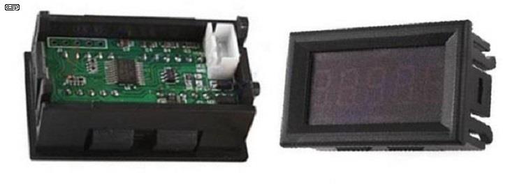
Figure 7 - Example Voltmeter Module
To make a completely self-contained unit, add a voltmeter module similar to that shown above. The one I used has 4 3/4 digits, and can display up to 4.3000V (yes, I thought that was odd too) and has an effective resolution of 100µΩ. However, it does not show negative values, so setting the offset is made a little harder than it should be. I compared the readings with my precision bench multimeter that can measure down to 1µV on the millivolt range, and the results were surprisingly consistent. These meter modules are available from ebay for under $10.00 which is very reasonable considering the accuracy.
Low Resistance White Paper - Tektronix
OP07 and LM385 Datasheets
Most of the concepts shown are standard opamp applications, and all have been covered in detail in other ESP articles and/ or projects.
 Main Index
Projects Index
Main Index
Projects Index| Copyright Notice.This article, including but not limited to all text and diagrams, is the intellectual property of Rod Elliott, and is © 2016. Reproduction or re-publication by any means whatsoever, whether electronic, mechanical or electro-mechanical, is strictly prohibited under International Copyright laws. The author (Rod Elliott) grants the reader the right to use this information for personal use only, and further allows that one (1) copy may be made for reference while constructing the project. Commercial use is prohibited without express written authorisation from Rod Elliott. |