
|
| Elliott Sound Products | Project 167 |
It's not uncommon for hi-fi systems to have a valve (tube) preamp, because there is still a 'mystique' about valve gear that some people find alluring. The valve preamp is then (in many cases) followed by transistorised power amps, electronic crossovers, or other equipment that doesn't like high voltage applied to its input circuits. Unfortunately, a valve preamp can not only produce a signal level that's quite capable of damaging the input stages of opamps or power amps, but when power is applied the output voltage swings to the full B+ supply rail until the cathodes heat up and the valve starts drawing current.
While the available current isn't high (it's almost always limited by the valve's plate resistor of between 47k and 100k), a 250V supply can still produce an instantaneous current of somewhere between 2.5 and 5mA or more. Most opamps have some degree of input protection, but certainly not all do, and the high voltage applied can cause damage to the input stage. There can be a more serious problem if the valve circuit has a cathode follower output, because while the voltage rises fairly slowly, the valve can provide significant current into the protection circuits with high level signals.
The situation is a great deal worse if a MOSFET source follower is used. It has no cathode that needs to warm up, and it can provide a large peak current at power-on. The current is limited only by the following stage's input capacitor and/ or the valve gear's output cap. It's to be expected that if a MOSFET is used, the output cap will be larger than 'normal' because the whole reason for using a buffer is to ensure a low output impedance, and the ability to drive common opamp or transistor stages. These usually have an input impedance of less than 100k (22k is common for a lot of ESP circuits). While the use of a MOSFET follower isn't especially common, there are several circuits available. Unfortunately, most of the circuits you'll find fail to address the high-voltage, high-current output pulse at power-on, and don't include any protective measures. Good DC filtering means that the voltage rise is usually slower than the estimates provided here, so its effects aren't as great. The doesn't mean that you don't need a little extra circuitry to ensure that the output is 'safe' under all conditions.
In order to protect the following input stages, some additional circuitry is necessary. This short article describes the options, and also shows a recommended MOSFET follower design.
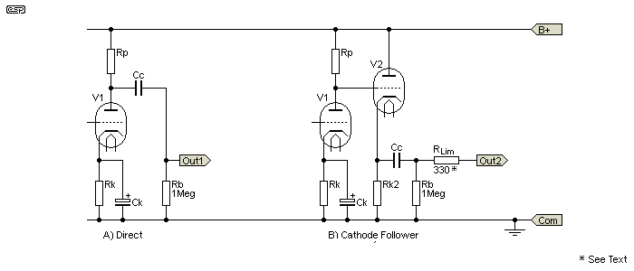
As noted in the intro, there are two common (and one less common) possibilities for valve stages that are intended to drive external equipment. A direct output from a triode stage can normally only be used if the load impedance is high - typically between 470k and 1Meg or so. Cathode or MOSFET followers allow the valve to drive much lower impedances, but generally not less than 10k. For flexibility, the coupling capacitor (Cc below) needs to be a suitable value to ensure there's no rolloff at the lowest frequency of interest with 'typical' load impedances. A reasonable value for the two versions with followers is around 2.2µF, which allows a -3dB frequency of 10Hz with a 10k external load.

Figure 1 - Valve Output Stages (Direct & Cathode Follower)
In each case above, values for the valve stage aren't included, because they depend on the circuit used. Rp is the plate resistor, Rk is the cathode resistor, Ck is the cathode bypass cap, Cc is the coupling cap, and Rb is the 'bleeder' resistor that ensures that Cc charges normally if a load isn't connected. The direct valve stage will swing its output close to B+ when power is applied, and current is limited by Rp. The cathode follower output voltage is zero when power is applied, and gradually rises to the normal DC output voltage as the cathodes heat up to working temperature. This a a fairly slow process (at least a few seconds), so transients at the output are largely eliminated by the output coupling capacitor (Cc). RLim is included to isolate the cathode follower from capacitive loads. It's usually not needed, but it does no harm and helps to limit the peak current if a voltage clamp and/ or mute relay is used (as shown in Figures 3 and 4 respectively).
With the direct stage, the maximum current will usually be no more than around 5mA (limited by Rp), but can usually be expected to remain below 1mA with a 47nF output capacitor (Cc). The cathode follower is inherently slow because the cathode has to heat up, so it's unlikely that a destructive switch-on current can be produced. The MOSFET follower is another matter - it can easily provide 35mA or more through a 2.2µF output cap (into a low impedance). Current into a 10k load will peak at perhaps 20mA or so, with a peak voltage of 90V across the load. That will damage most opamps and power amp input transistors.

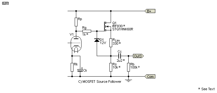
Figure 2 - Valve Output Stages With MOSFET Follower
The MOSFET follower is dangerous to semiconductor loads, because the voltage will rise to the full B+ when power is applied, and there is typically no form of current limiting in most circuits you find. RLim is a limiting resistor, intended to prevent the MOSFET from delivering excessive current if the output is shorted by a muting circuit (as shown below). The value depends on the value of the source resistor (Rs) and the type of MOSFET, and needs to be selected for the circuit you use. The values shown are simply a suggested starting point - they are all dependent on your specific requirements, the actual circuit you use, and the type of MOSFET. As shown, expect a maximum current of about 25mA.
You might imagine that the gate capacitance of the MOSFET would cause excessive high frequency rolloff, but that's not the case. The capacitance is effectively 'bootstrapped' by the source follower action, so it effectively disappears. This isn't to say that there is no effect of course, but it doesn't come into effect until typically well over 30kHz - depending on the source impedance and MOSFET.
The MOSFET is a good option, as it doesn't need a heater supply, and an IRF830 or similar will work very well. This is suggested only because I have some, and that's what I used to test the circuit. Ideally, you'd use a lower current device, for example FQN1N60CTA or STQ1HNK60R (600V, 300-400mA, both TO-92 package). There are quite a few suitable devices to choose from, and the linked datasheet is just one example. The voltage rating only needs to be greater than your supply voltage maximum. This occurs before the valves start conducting, and can be up to 20% higher than the operating voltage.
MOSFETs have a much higher gm (mutual conductance) than valves, and have a lower output impedance and higher drive capability. To be able to use it safely, we need to make sure that it can't produce dangerous voltage or currents that will damage the following circuitry. Inclusion of the limiting resistor (RLim) isn't mandatory but is highly recommended, and it will typically be around 330 ohms for a 10k source resistor. This will limit the peak current to less than 30mA, but this depends on the MOSFET's characteristics, and needs to be verified and/or adjusted in practice. If you don't include RLim, a 100 ohm series resistor should be used at the output to minimise the risk of oscillation with capacitive loads (e.g. shielded cables). Rg (the gate resistor) is included to prevent oscillation - it will usually be around 560Ω - 2.2k.
There is one thing that can mitigate the peak voltages and currents, and that's the use of a valve rectifier. These have a slow turn-on because the cathode or filament takes time to get to operating temperature, so there is no sudden rise of voltage. However, I never recommend them for anything because silicon diodes are a much better choice for any rectifier, but the voltage does rise very quickly when power is applied. Valve rectifiers have no place in any equipment IMO, so we need to look at sensible ways to ensure that high voltages or currents are never allowed to reach the equipment's output connectors.
Ultimately, the rate of rise of the B+ supply is limited by the time constants of the filter circuits, so the values given should be considered worst case. In most preamps there will be enough filtering to slow down the B+ voltage rise enough to ensure that there's little extraneous noise when the system is powered on, but including protective circuits should be considered best practice, and the added cost is minimal.
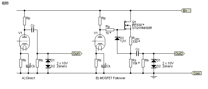
The simplest way to prevent damaging voltages or currents from reaching external equipment is a voltage clamp. This needs to be nothing more sophisticated than a pair of zener diodes, wired in series. You may think that only one is needed, but that's not the case, and a single zener will cause excessive distortion. Especially with the cathode or MOSFET followers, they can provide a signal level of well over 10V RMS if given a high-level input signal (whether accidentally or otherwise). Since no 'normal' circuit ever needs more than around 5V RMS as an absolute maximum, a pair of 10V zeners is all that's necessary to limit the maximum voltage. Unfortunately, a simple zener diode clamp will not stop the valve gear from making a very loud noise through the speakers if it's turned on after the power amplifier(s).

Figure 3 - Simple Voltage Clamp
Use of a voltage clamp is recommended with any valve circuit that's intended to power 'solid state' equipment. Cathode followers are less of a problem than MOSFETs, because a valve warms up slowly, and has a relatively high output impedance. If you use a MOSFET, the output voltage will increase to almost the full B+ voltage at power-on. A pair of 10V zener diodes will ensure that the output voltage cannot exceed ±10.6V (7.5V RMS), which is almost always far in excess of the voltage needed by the external circuits. Most valve preamps are designed for output levels of 2-3V RMS at most, and that's sufficient to drive virtually any power amp to full power. An amplifier with 27dB of gain will produce (or attempt to produce) over 260W into 8 ohms with a 2V RMS input. 10V zeners are suggested because their leakage will be very low so the high impedance signal is not affected, but the voltage is low enough to ensure safety against damage.
With the direct output valve stage or when you use a MOSFET follower, when power is applied, the voltage at the plate of the final valve rises quickly to the full supply voltage. It will be slowed down to some extent by the filtering circuits in the preamp, but this will rarely be enough to prevent a low-level 'thump' from the direct circuit, and a significantly more pronounced (and possibly destructive) 'THUMP' with a MOSFET follower. In these cases, a mute relay will eliminate all noise. The clamp is still needed to protect against very high signal levels.

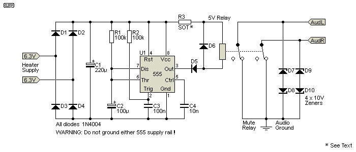
Figure 4 - Voltage Clamp And Muting Circuit
By adding a mute circuit, nothing will get through until the mute is released. The easiest and most effective way to mute any signal is to use a relay. They may be 'old' technology, but they are also extremely effective, simple to implement, and provide close to infinite muting. Ideally, the relay will be set up so its contacts short the signal when it's not powered, so the default will always be that the signal is muted until the timer that operates the relay has operated.
A 555 timer is ideal for the purpose. The trigger is pulled high, delayed by C3. As the circuit powers up from the 6.3V heater supply, the 555 sees the trigger voltage as being low, and it starts allowing C2 to charge. The time is set by R1 and C2, and as shown is around 9 seconds. C2 should be a low leakage electrolytic for predictable timing, and may be increased in value for a longer mute time. The output of the valve (or MOSFET) stage is shorted to audio ground to allow coupling capacitors to charge, and when the relay is activated, the contacts open and the audio outputs are enabled. The 10V zener diodes limit the maximum possible output voltage to ±10.6V (7.5V RMS). With typical audio levels of around 2-3V RMS, the zeners will contribute little or no measurable distortion, assuming a source impedance of 10k or less. Even with a 100k source impedance, there should be no noticeable increase in distortion at normal signal levels.
The filter cap (C1) should be the smallest value that works reliably. This ensures that the relay releases (and re-applies the short) as quickly as possible after power is removed. With most valve equipment, power-off is fairly well behaved, but there can still be a significant (negative going) 'DC' pulse at the output as the B+ voltage collapses. While this is most unlikely to ever be destructive, it's still best avoided.
Because the supply voltage derived from the 6.3V heater winding will be higher than the relay's 5V coil voltage, add a series resistor (R3), selected to provide 5V across the relay. For example, a relay with a coil resistance of 160 ohms will need an 86 ohm resistor (use 82 ohm, 0.5W).
Make sure that the circuitry around the 555 is not grounded. The 6.3V winding is usually floating or has a centre tap to ground to minimise hum, so the 555 circuit is also floating. The relay provides the necessary isolation between the 6.3V winding and the audio, and the audio wiring must be well separated from the 555 so there's no hum picked up. Keep the 555 circuit away from heat sources such as power resistors or valves.
There are really two separate parts to this project idea. The first is to show the use of a MOSFET buffer rather than a cathode follower where a low output impedance is required. The second is to show a handy voltage clamp and muting circuit, that's ideal for use in a valve preamp. The combination of the two will allow any valve preamp to safely drive opamps or transistor power amps, without risking damage to the input circuitry.
There is no PCB for any of the circuits shown here. Because there are several ideas rolled into one project, there's almost certainly no real need for PCBs, and it's unlikely that any will be produced. The necessary parts can all be assembled on a piece of tag strip. If you include the 555 mute circuit, it can easily be made on a small piece of Veroboard. If there is sufficient interest, I may make board(s) available, but I doubt that will ever happen.
The main point of this article is to inform valve enthusiasts to the real benefits of using a MOSFET buffer, and to alert users to the potential for damage if valve gear is connected to opamps or transistor circuits. Provided the outputs are derived from valves alone, you are usually fairly safe, but beware if you decide to use a MOSFET follower. Even a standard valve stage as shown in Figure 1 (A) is capable of causing damage though, so you need to be aware of the risks.
Any valve preamp can generate a very high level output signal if there is a faulty lead, or if a lead (using RCA connectors) is inserted or removed while the system is operational. Whether deliberate (no, I don't know why either  ) or accidental, the output level can easily exceed the allowable input range of most opamps and while their internal protection might be enough to protect them from damage, it also might not. The voltage clamp solves this, by limiting the maximum level to a safe value.
 Valves Index
 Main Index
 Projects Index
| Copyright Notice.This article, including but not limited to all text and diagrams, is the intellectual property of Rod Elliott, and is Copyright © 2016. Reproduction or re-publication by any means whatsoever, whether electronic, mechanical or electro-mechanical, is strictly prohibited under International Copyright laws. The author (Rod Elliott) grants the reader the right to use this information for personal use only, and further allows that one (1) copy may be made for reference while constructing the project. Commercial use is prohibited without express written authorisation from Rod Elliott. |