

|
| Elliott Sound Products | Project 163 |
Most preamps will use a simple rotary switch to select the desired input. This is convenient and fairly cheap, but you need a multi-position two-pole switch, and wiring all your inputs to it can be tedious (to put it mildly). There really isn't a 'friendly' way to do it, and it's made harder if the switch is at the front of the cabinet because all wiring needs to be shielded to prevent noise.
One can use an extension shaft (such as the ES-250 from ESP) which allows the switch to be located at the rear of the enclosure. This makes wiring easier because all leads are very short, but you still need the multi-position two-pole switch, with as many poles as there are inputs. In most cases, rotary switches can only provide a maximum of six double pole switches, and if you happen to need more inputs then you're out of luck. Even when located at the back of the preamp chassis, they are still a pain to wire.
By using relays to perform the switching, you only need a single pole switch, and they are readily available with up to 12 poles - enough for everyone I expect. Once relays are used, you can also use electronic switching, which provides the ability to use a remote control, touch switches or any other arrangement that can be adapted to switching relays. I haven't included touch switches here, but may add a touch switch project at a later date.
Typical inputs are shown in brackets in Figure 1, but naturally these would be adapted to suit your needs. The most common would be Phono, CD, DVD, Auxiliary (Aux.) and TV, but many people have other input requirements as well, so five may not be enough. A rotary switch allows up to 12 inputs, and various logic systems as shown here may allow up to six or nine without change, and potentially many more if you need them.
It's also possible to use CMOS analogue switches instead of relays (e.g. 4066), but IMO they do not qualify as hi-fi. You also need to provide ±6V supplies so the inputs and outputs of the switching module don't have to be AC coupled. If there's enough interest I will add a circuit that uses analogue switches, but if it helps you to decide, I would not accept them in my system.
The following schematic shows how you can switch relays using a rotary switch. It's a very simple circuit, and you can use up to 12 relays with a commonly available 12 position rotary switch. Only three of five positions are shown, and if you need more you simply increase the number of relays. Each relay is DPST (double-pole, single-throw), but you can use DPDT (double-pole double-throw) relays as well. The Left and Right inputs are connected via the normally open contacts of each relay.
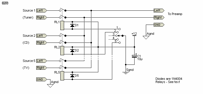
The relays will typically use 12V coils, but there's no reason not to use 5V (or 6V) relays if they are easier to get. The advantage of 12V relays is that they draw less current, with a typical miniature 12V relay drawing about 34mA, while a 6V version of the same type will draw around 110mA. Of course, it's not a big deal, because only one relay is ever energised at any one time.
The diodes across each relay coil prevent the relay coil's back-EMF from causing audible clicks and pops, and should always be included. Note that there are two earth/ ground connections, 'Agnd' (analogue ground) and 'Sgnd' (switching ground), and these should not be joined. The relays need to be powered separately from the analogue preamp circuitry so that there is no interaction between them that may create switching noise. This is covered in more detail below.
In general, completely sealed relays are preferred. Because they are sealed, contact contamination is all but eliminated. Ideally, gold contacts would be nice because gold doesn't tarnish, but these relays are usually fairly expensive - assuming you can actually get them. I've used standard sealed relays for signal switching and muting in many projects, and have never had a failure with the hermetically sealed units that are readily available.
The next option is to use active switching. It's not necessary with a rotary switch because the contacts can easily handle the relay coil current, but if you think you may prefer electronic push-button selection then the relay coils need to be switched with a transistor, MOSFET or dedicated switching IC.
There are many transistors that can be used to switch relays, but low power MOSFETs have several advantages. Chief among their benefits is the fact that the gates draw no current, so if you use electronic switching it becomes possible to maintain power using a 'super capacitor' - typically these are 1F at 5.5V maximum, and one can hold up CMOS logic circuits for weeks, so your preamp won't 'forget' which input was used last. It's also easy to preset one preferred input that will be selected each time the unit is powered on.
If you were to use MOSFETs, ideally each should have a zener diode installed between gate and source. The zeners will ideally be installed first, so the MOSFET gates are protected from static damage, even while they are being installed. This is a relatively expensive option though, so you can use 1N4148 diodes from the gate to the +Ve supply instead. Provided the MOSFETs and switching circuit are located close to each other (no long leads) the diodes can be omitted (but at your risk). Although the 2N7000 is not characterised as a low gate threshold MOSFET, a 5V gate voltage is normally more than sufficient to switch a 12V relay with a coil current of less than 50mA.
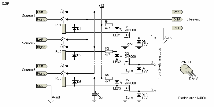
The LEDs are optional, as are the gate diodes for the 2N7000 MOSFETs. LEDs would normally be located on the front panel to show which input is selected, and in the interests of minimising current drain if a backup supply is used, they do need to be switched by the MOSFETs. They have been shown with 4.7k resistors for a current of about 2mA, but this can be adjusted as desired. Excessively bright illumination can be very annoying in a darkened room, so use a value that gives a comfortable output. While a single resistor can be used for all LEDs, the ones that are turned off will be subjected to an excessive reverse voltage, which is not recommended.
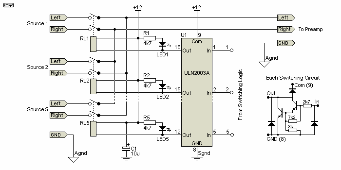
Depending on the type of logic you end up using (CMOS, PIC, etc.), you may decide that it's better to use bipolar transistors rather than MOSFETs. They are certainly cheaper and far easier to get, and they don't have super high impedance inputs that can be destroyed by a small static charge, so zener diodes aren't necessary. The only real difference between the two circuits is the switching device and the load it presents to the driving IC.
Rather than messing around with a bunch of discrete parts, you might prefer to use a multi-way relay driver IC. One that's suitable and quite inexpensive is the ULN2003A, a seven channel switching IC. It includes base input resistors, Darlington transistor switches and relay coil protective diodes in a 16 pin package, and what you see above is 'it' - nothing else is required. It's hard to get a simpler circuit to drive the relays. The equivalent circuit of each switching channel is also shown.
While the relays have been shown selecting inputs, they can be used for anything else as well. How they are driven depends on what you wish to achieve, and there are several logic systems shown below that can be used. You can use more than one if you wish, for example if you need to be able to bypass tone controls or switch in an infrasonic ('subsonic') filter. The way the logic works depends on what you want to do. For the ultimate flexibility, using a microcontroller or PIC means that you can change the functionality in software rather than having to re-wire the circuit(s).
This is a real can of worms. There are many options, but the use of standard CMOS logic is the most forgiving - especially in terms of longevity. As noted earlier, CMOS ICs have a very low static current drain and can be held up with a super cap or a rechargeable Li-Ion cell (ideally charged to a maximum of no more tan 4.1V). Without some form of hold-up circuit, the logic will forget which input was active, and the desired input will have to be selected each time the preamp is turned on. Alternatively, you can ensure that your preferred input is selected when the preamp is turned on with a 'pre-selection' circuit. CMOS logic typically requires several DIP packages, along with other support components. Ensuring that de-selected inputs are, in fact, turned off can require a surprising number of parts, because the latching circuits have to be reset when a different input is selected.
The use of a microcontroller is pretty much standard these days in commercial products. This isn't always a good thing - yes, you get countless options and serious processing power, but if it dies in 5-10 years time, you probably won't be able to get a replacement. This can render an entire preamp useless, unless there's some way that an alternative controller can be adapted. A microcontroller also gives you the option of using digital 'pots' - IC based volume controls. Again, a means of remembering the setting is needed so that the level will be as you left it, and you also need a display to show the level setting, and/or other settings that would otherwise be shown by a knob with a pointer.
Using a simple microcontroller can make the switching quite straightforward, but ultimately it depends on the switching interface. Separate buttons for each input are easy, but you may end up with quite a few buttons and LEDs on the front panel. Using a single button that steps through the inputs sequentially is simple, but not very ergonomic if you have a lot of inputs (many button presses may be needed to select the input you want). You can also use Up/Down buttons, so you can step the inputs in either direction, and this the approach I've taken.
There are many different CMOS counters that are potentially suitable, but most have binary outputs so the outputs need to be decoded before they are useful. It's also possible to use simple bistable (flip-flop) circuits, but then you usually need to provide additional logic to make them do what you want. It turns out that using a microcontroller is actually the simplest, and the natural choice would be a PIC. Of those available, the PICAXE is one of the easiest to program (by a long way, provided you are comfortable with BASIC). Naturally, any PIC can be used - the drawing below is completely generic, hence there are no pin numbers.
For clarity, I've used the term 'channel' for a pair of inputs (left and right). Therefore, channel 1 might be for a phono preamp, channel 2 for a tuner, etc. The following drawing also shows pull-up resistors for the switch inputs, but these may not be needed, because some PICs and micros can provide an internal pull-up (or down) when pins are designated as inputs.

As always, a drawing of a PIC is not in the least bit helpful, other than to show how inputs and outputs might be connected. The specific pin numbers for in/out are all determined in the software downloaded into the PIC, as it the overall behaviour of the system. In some cases, it's possible to save the last used configuration in non-volatile memory, and that removes the need for battery backup. However, you do need a way to detect that the supply has been removed, and provide enough 'juice' to keep the device working until it's saved the data. This should normally only take a few milliseconds. The required circuitry has not been included in the drawing, because it depends on the PIC or micro used.
Of course, you can also use an Arduino, Raspberry Pi, Beaglebone, or any other micro to control the relays. With any of the advanced options, you'll be able to control a lot more than a few relays. However, in the case of DIY equipment, it's normally expected to work forever after it's been built. The more 'smart' functions you have, the less likely it becomes that your preamp can be repaired once the micros, LCD panels, digital pots or other parts become obsolete. Of course, they may work flawlessly for many years, but once they're gone, they really are gone.
The programming depends on the PIC or micro that you use. The essential functions are selection push-buttons (e.g. increment/ up, decrement/ down) and enough outputs to be able to switch the number of inputs you use. At most, you'll probably never need more than around eight input channels, and most people won't need that many. A pseudo-code program is shown below, and is readily adapted to any programming language. 'channel' is a variable that represents the set of outputs, so output(channel) = 1 means the output is high (5V), and RL1 in Figure 2 or 3 will be turned on.
Start:
channel = 1                 ;select first channel
output(channel) = 1         ;at power on channel 1 is selected
loop:
  if button1 = 1 then       ;move to the next output (increment)
    output(channel) = 0     ;turn off old channel
    channel = channel + 1   ;increment channel number
    output(channel) = 1     ;turn on new channel
  end if
  if button2 = 1 then       ;move to the previous output (decrement)
    output(channel) = 0     ;turn off old channel
    channel = channel - 1   ;decrement channel number
    output(channel) = 1     ;turn on new channel
  end if
  delay(500)                ;500 millisecond delay
goto loop
I've only shown pseudo code in the most simplistic format, but the principles are the same regardless of the way the code is written or the programming language that's used. I haven't shown any specific routine to initialise the active channel (other than selecting 'output(1)' at start-up) or save the one that was last used. Also missing is de-bounce code, which is needed because switches don't make a single closure when pressed. There can be several connections and disconnections, which will cause problems. The 500ms delay might be enough or it might not. There are far more elegant ways of achieving the same result, but for a simple application, the simplest possible code is recommended. It doesn't need to be elegant, it just needs to work reliably. It will also need some additional code to ensure that the 'channel' variable can't be decremented to less than one, nor can it be incremented beyond the total number of channels.
There is also nothing to prevent silliness from happening if both buttons are pressed at the same time. With the pseudo code shown, there will be no net change, because the next then previous channel will be selected, leaving everything where it was (but perhaps with some relay clicking). This article is not about writing the code, as that's something that the constructor has to sort out.
The alternative to the above arrangement is to use a separate switch for each channel. A touch of a button, the logic circuit switches to that channel and its LED comes on, and any other channel is disconnected. The logic flow is different of course, but it only requires a duplication of some of the pseudo-code shown above, with a separate section for each button. Most PICs have more than enough memory space for crude but simple code that is easy to follow.
There will be plenty of people who really, really would prefer to use a simple logic based system, without the need for a PIC and the obvious requirement to program it. There are several options, but they all need a fairly significant number of additional parts because the signal has to be 'steered' to all the right places at the right time. The obvious choice is the use of bistable (flip-flop) circuits, and the 40174 CMOS hex D-type flip-flop is one of the few choices that allow a single chip to handle up to 6 input channels. A power-on reset (POR) is required with most logic circuits, because they can be in an invalid state when power is applied without it.
Note: There is one major difference with the next three circuits - each channel uses a separate switch. Up-down operation is possible, but the circuit becomes overly complex because of the additional gates needed to make an up-down counter function. Since these counters are also binary, the outputs have to be decoded before they are useful. This adds even more parts, and it becomes unwieldy very quickly. Instead, simple latches (or flip-flops) are easier to use, although Figure 7 is an exception.
The circuits aren't as simple as you might prefer, because there are several requirements that must be met. Firstly, we need to send a voltage to an input and generate a clock (or reset) pulse when a button is pressed. The clock signal must be delayed slightly (a few microseconds is all that's needed). A D-type bistable circuit requires that the data are present at the input(s) for a defined minimum period before the clock pulse arrives, otherwise the flip-flop will not change state. In the case of the 40174, it needs about 20ns set-up time, and the data must be held for at least 20ns after the clock signal. Fortunately, the device is edge triggered, but has no maximum risetime specification for data or clock signals. This means that the clock signal can rise as slowly as we like.
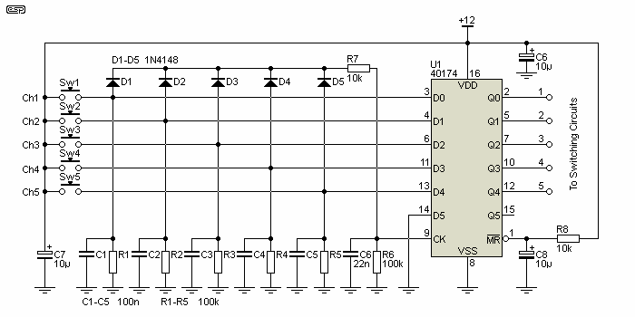
The pin numbers shown above refer to the 40174, but each pin is labelled as to its function so it will be easy to transpose to the 4013 if preferred. The main difference between the two devices is that the 40174 has a common clock and master reset, and the 4013 has separate reset and set pins for each flip-flop. This is but one method you can use - there are quite a few alternatives, but the essential functions aren't very different.
Ok, it looks a bit complex, so how exactly does it work? Most of the circuitry is duplication, and each channel has a push-button. When a button is pressed (assume Sw1), voltage is applied to pin 3 of the 40174, and via D1 and R7 to C6 (10k and 22nF respectively) and the clock input. R7 and C6 delay the clock just long enough to ensure that the voltage from Sw1 (held up for a few milliseconds by C1) is seen as a valid high input to pin 3 (D0 - Data 0).
After about 10 milliseconds after the button is released, the voltage on pin 3 will be below the CMOS threshold (about 6V with a 12V supply), but the signal is now latched by the flip-flop and Q0 (output 0, pin 2, channel 1) remains high. When a different button is pressed later on, the process repeats, but only the input (and therefore the output) corresponding to the pressed button will be activated. The circuit relies on the diodes to generate the clock pulse, and the 100nF caps (C1-C5) to hold the voltage for long enough to ensure it's latched.
There are also the usual decoupling caps (C6 and C7), and finally a 'master reset' (a POR [power-on reset] circuit) which turns off all inputs when power is applied. This is provided by R8 and C8, with C8 forcing the reset pin low until it charges to about 6V, which will take a little under 100ms. Note that there is another flip-flop (U1.15, Q5) that can be used as well - simply duplicate the input circuitry. This provides up to six inputs. If preferred, you can use the 4013 dual D-type flip-flop, but to get 6 input channels you need three ICs rather than just one.

If you'd rather use 4013 dual D-type flip-flops, then that's easy enough. The 'set' pin of each flip-flop is simply grounded, and the reset different. When power is applied, the reset pins are pulled high momentarily by C7, and that forces all outputs to zero. Otherwise, the circuit performs in exactly the same way as the one in Figure 5. Only three channels have been shown, but again the switches and other parts are simply duplicated. Using three 4013 ICs allows up to 6 channels, but it can be extended to as many as you need.
These circuits are immune from contact bounce from the switches. It doesn't matter if the signal and clock are applied once or several times, the correct channel will be selected. Be aware that if two (or more) switches are pressed at the same time, then the appropriate channels will all be selected and joined together. This can be prevented, but at the expense of even more circuitry. These circuits are already complex enough - especially when compared to using a microcontroller or PIC. The following circuit does include a lock-out function. If more than one button is pressed, only one output will be activated.
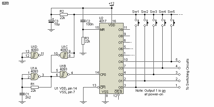
This version is interesting for a number of reasons. It uses a free-running oscillator at about 24kHz (U1A) to provide a clock signal, the output of which is normally gated off by NAND gate U1B. The gate's input at pin 5 is held low, because the switch bus is normally high (due to R2). When a button is pressed (other than the currently selected channel) the switch bus goes low, and the oscillator signal is enabled via U1B. The outputs cycle through until the output corresponding to the pressed button goes high. This stops the oscillator pulses, and the counter remains at the selected output. U1C is used as an inverter, and U1D is not used. The button must be kept pressed for long enough to ensure that the clock cycles through all outputs, but that happens in less than 500µs with the values shown.
Outputs will pulse high for a very short period (around 41µs) while a button is pressed, but the signal is not present for long enough for a relay to even think about changing state. The recommended relay switching circuit is that shown in Figure 2 (using 2N7000 MOSFETs) to minimise loading on the counter outputs. Output 0 (Q0) is the default, as it is selected when power is applied due to the power-on reset, and it's re-engaged by Sw1. When wired as shown in the drawing, output 1 is on and all others are off when power is applied. If you don't want a default on position, don't use Q0 - simply move all outputs up to the next 4017 output. Output 1 will then be wired to O1 and so on.
C2 and R3 are the reset components - when power is applied, the master reset (U2, pin 15) is pulled high, forcing all outputs except Q0 to zero output. The circuit can be operated from 5V is preferred, but CMOS is quite happy with a 12V supply so a regulator hasn't been included. Make sure that the clock oscillator (U1A) won't send high frequency noise into your audio circuits - it may be necessary to provide a simple earthed metal shield around U1 to minimise radiated noise. There is no requirement for R/C networks or 'steering' diodes, so the circuit is simpler to implement and requires less PCB real estate.
All of the above circuits can be left powered permanently, which saves the problem of having to use additional circuitry to provide standby power. When the preamp is turned off, you'll remove power to the relays and preamp circuitry, but keep the power on for the CMOS. Because they draw negligible power, the only 'phantom' power you'll pay for is due to the transformer that runs your preamp, and that will consume a few watts at most. The oscillator in Figure 7 should be disabled in standby - simply connect one of the U1A gate's inputs to the switched 12V supply, and it will shut down when that voltage disappears. Make sure that the switched 12V is no greater than the un-switched supply or the gate may be damaged.
This is one of the more 'traditional' circuits using CMOS. In its favour is apparent simplicity, but the number of passive support components (diodes and resistors) makes it more difficult to implement than the other circuits shown. As noted below, the number of diodes escalates quickly as more inputs are added. The diodes can be replaced by OR gates, but that does little to reduce the total parts count.
I didn't include this when the project was published, but a reader is using the circuit shown (and let me know) and I decided that others might find it useful for simple applications. The circuit follows that of the reader's circuit closely, but this is a fairly common circuit and there are few ways that it can be done differently. The main limitation is the need for all those diodes, the reason that only 3 selections are shown. If you wanted to use the fourth section of the 4043, you need to add more diodes - 12 are required for a 4-way circuit. Each switch requires n-1 diodes, where 'n' is the number of switch positions. For four switches, each needs 3 diodes, so there would be 12 in all (not counting the final diode that selects the default channel at power-on).
The diodes and resistors take up far more space than the IC, even for a 3-way circuit. Expansion is almost an exponential function, and going to 5 positions means you'd need 20 diodes and 10 resistors (again not counting the power-on circuit). Note that the power-on circuit is not optional! It's needed because when power is applied, there is no guarantee that the flip-flops will start in any particular way (for example, with outputs low). Whichever input is selected by the jumper will set that output high, and apply a reset signal to the others so they are forced low. All diodes are 1N4148 or similar, and the resistor values can be varied (higher or lower) by a factor of at least 2 without changing the way the circuit operates.
The 4043 is a quad R-S (reset-set) latch. It has a tri-state output but that's not used here. You could use the 'EN' (enable) pin as mute if you wanted. Taking pin 5 low disables the outputs without affecting the logic state, so it will mute the output by turning off all audio inputs, reverting to the selected channel when pin 5 is returned high.
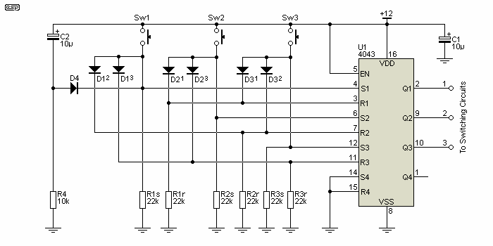
Diodes are numbered to show which circuit they reset, so D1² is related to Sw1, and resets the second flip-flip. Resistors are numbered to show which flip-flop they are used with, and (for example) R1 relates to the first flip-flop. The resistor suffix denotes the input function, so the 's' resistor is for the 'set' input, and 'r' denotes the 'reset' input. Circuit operation is almost self-explanatory. When (say) Sw2 is pressed, the Q2 flip-flop is set. At the same time, D21 resets Q1 and D23 resets Q3, so only Q2 is active.
The 'POR' (power-on reset) has a time constant set by C2 and the resistors (there are effectively four in parallel, with some joined via diodes) so the pulse generated has a duration of a little over 25ms. As shown, channel 1 is selected at power-on, but diode D4 can be connected to any desired input to make it the default.
This general class of circuit (excluding the CMOS IC) is an example of one of the earliest forms of logic, using diodes and resistors to form 'AND' or 'OR' gates. In this case, the gates are wired for 'OR' function, so the outputs (connected to the 4043's reset inputs) are activated if one OR the other input is forced high by a selector switch. The resistors are necessary to ensure that the CMOS inputs aren't floating, which can lead to erratic operation and/or excessive power dissipation.
This is not the only way this IC can be used for input selection. There is a trick that can be used to reduce complexity, but it relies on forcing the inputs to 'invalid' states for a short period. This doesn't mean that it will harm the IC or that unwanted outputs will occur. The basic arrangement is to force a reset on all flip-flops when a button is pressed, and relying on the button being held until the reset has passed. This reduces the number of diodes to 1 per channel, and adds a timing circuit similar to that shown for generating the clock pulse in figures 5 and 6. This arrangement means a resistor, capacitor and diode for each input, but it's no longer an exponential increase of components when more inputs are added.
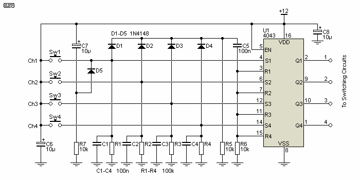
The amended circuit is shown above. All four latches are used this time, and the circuit is simplified by using a common reset bus. The reset signal is generated as C5 charges via one of the diodes and R6. The capacitors C1 to C4 are not strictly necessary, but they help hold up the selection bus if there is contact bounce in the switches. Power-on reset is provided by C7, R7 and D5, and can be connected to any desired input to make it the default.
For each additional input channel, you add one diode, one resistor, one capacitor and one switch. Naturally you'll also need more gates, as the 4043 has only four per package. Compare this with the Figure 8 circuit, where to add one channel means adding a potentially large number of diodes (n-1 x channels), and ending up with a circuit that will be very unwieldy and difficult to assemble without errors. Imagine a six channel version - you would need 30 diodes!
Another alternative is to use auto-switching. When audio is detected on an input, the switching system automatically selects that input and disconnects any other that may have been used. The disadvantage of this is that you might have two active signal sources, and an automatic selection system doesn't know which one you want to listen to. It will either remain locked on the original source until it's turned off or select the new signal and disconnect the original. A lockout system is needed, or it may try to connect both together or switch back and forth between the two.
The circuitry needed isn't complex, but you need a detector for each input, so there will be many opamps and other components and it will not be inexpensive to build. An audio detector such as that shown in Project 38 will work in most cases, and some form of lockout circuit may be needed so that multiple active inputs won't be shorted together. This won't be a problem if unused inputs are always turned off at the source. Naturally, the relay shown in the project will switch the audio, and not mains.
This isn't an arrangement that will be included here, unless I get enough requests to make it worthwhile. Of the systems that I've seen that use auto-selection, most don't seem to work as well as they might, and getting it right isn't quite as easy as it may seem at first. Even selector circuits for HDMI don't always work reliably, even though they can detect the 5V DC that's part of the HDMI specification. I know this because I have one, and it generally requires manual selection with a push button.
The relays are easily wired up on Veroboard or similar, and the only thing that really needs to be done carefully is to separate the ground for the relay and logic or microcontroller from the analogue ground. It's unlikely that there will be enough interest to warrant a PCB, and it can only be used for the relays and their switching transistors (and ancillary parts), plus the audio inputs and outputs. Including the switches is too limiting, and would mean that the selection and placement of switches would be fixed, reducing flexibility for the panel layout.
If you use a PIC to control the relays, that will also be fine with Veroboard, and an Arduino or similar microcontroller already has a PCB, and only needs a supply voltage and connections for the switches and outputs to the relay board. There's no reason that everything can't be on the same piece of Veroboard, but make sure the PIC or micro is well away from the audio buses so there's no noise pickup.
If you use a PIC or CMOS, be aware that they are subject to static damage, so avoid touching pins without making sure that any static charge you are carrying is discharged. Use an anti-static wristband, and touch a ground connection on the board before anything else.
The most challenging part of the build will be to arrange nice-looking push-buttons. You might consider making a complete frame using a 3D printer if you have one, and that could be made to look very nice. They can be fabricated a number of ways, or commercial 'mini-tactile' switches can be used with buttons of your choice. Remember that you need a LED to indicate which input has been selected, because there is no other indication.
No other reference material was used for this article. Most of the concepts are basic knowledge. There is a circuit that uses a 40174 IC on the net, but it's not referenced because it won't work, and I'm not about to send readers off to look at a circuit that will blow up the IC the instant power is applied. The drawing shown in Figure 7 is based on one I found on the Net, which looks like it was stolen borrowed from Silicon Chip magazine (it has the same drawing style as used in the print edition). The date of publication is not known.
 Main Index
 Projects Index