
|
|
| Elliott Sound Products | Project 162 |
A voltage controlled oscillator (VCO) isn't something you need every day, and you may never have thought that you need one at all. You'd probably be right, but some things are just too interesting to ignore, and this is one of them. A few years ago, you'd simply get an IC that did almost everything for you - the NE566 was a good example, and needed few external parts to make a simple, high performance VCO.
Unfortunately, the NE566 (or LM566 which was an equivalent) is no longer available from any reputable supplier. You may be able to find them advertised on certain on-line auction sites, but they are not trustworthy sources and you have no idea what you'll get. Some advertise them for insane amounts of money ... way more than most people would be willing to spend. There aren't many alternatives either. There are a few PLLs (phase locked loop ICs) that are still available, but they aren't especially easy to use.
VCOs are used for tone generators, frequency modulators, clock generators, function generators, music synthesisers and frequency shift keying (FSK, a radio transmission system where digital information is transmitted via discrete frequency changes of a carrier wave). Being able to create a perfect triangle waveform means that a simple diode clipping circuit can be added to obtain a reasonably low distortion sinewave (less than 2% THD is possible).
One application that can be very useful is to use a VCO as a sweep generator for testing loudspeakers, crossover networks, equalisers, etc. For this, waveform purity isn't a major concern, but you do need a constant amplitude regardless of frequency. The input can be driven from a ramp waveform or manually, and it's not at all difficult to obtain a 10:1 frequency range. Greater frequency range is possible with careful design. The advantage of circuits like those shown here is that there are no glitches in the output, no matter how quickly or slowly the frequency is changed.
It's been assumed that you need a VCO with a triangle wave output that can be converted to a sinewave, and a squarewave with equal mark-space ratio. If these aren't high on your list of features then much simpler VCOs are easily constructed using a 555 timer or similar. There are also VCOs within PLLs, and many others intended for radio frequencies etc. Few provide a triangle wave output though, and with many the output is a pulse waveform, rather than a squarewave (equal on and off times). These alternative versions are not covered here. The reason for using a circuit like those shown below is - first and foremost - to be able to get a passable sinewave output. You can also use a function generator IC. Two that still seem to be available are the ICL8038 (Intersil) and XR2206 (Exar), but they are not inexpensive.
The output frequency vs. modulation voltage input is linear, so these circuits aren't useful for music synthesis unless a logarithmic amp is used to provide the control voltage. This isn't something I intend to include, and if that's what you need you'll have to look at designs specifically intended for use with synthesisers. The maximum frequency is also limited, so these circuits can't be used for RF applications.
To give you an idea of how simple it used to be, Figure 1 shows a NE566 VCO circuit. You'll find countless examples of this circuit on the Net, but since you will be unable to get a reliable source of the ICs it's a moot point. I've included it here purely for the sake of completeness and to show how easy it was to make a VCO a few years ago.
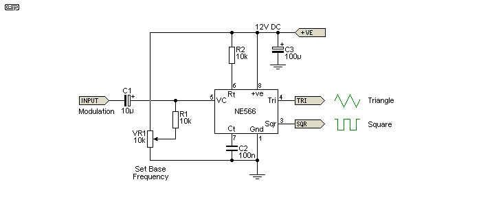
Figure 1 - NE566 Voltage Controlled Oscillator Schematic
The VCO itself only needs one resistor (R2) and one capacitor (C2) for timing. The control voltage input needs to be biased to some voltage that gives you the base frequency you need. This is the frequency obtained when there is no external modulation. The datasheet shows a pair of fixed resistors, but I've shown a pot that lets you set the base frequency. The modulation input will cause the frequency to change by a factor that is directly related to the input level. A positive modulation voltage causes the frequency to increase, and vice versa. C1 is selected to give response down to the lowest frequency of interest, and is less than 1.6Hz with the values shown.
The datasheet shows a formula for frequency, and with the values given in Figure 1 it works out to be 1kHz if the 'Set Base Frequency' pot is set for 6V. Unfortunately, I have no way to verify that because I don't have any NE566 ICs to hand.
In terms of FM, the frequency shift is called the deviation. The frequency change is related to the amplitude, and the rate-of-change is determined by the modulation frequency. In case you were wondering, the NE566 was never intended to be used as a modulator for FM radio. It can't oscillate at 100MHz, and the modulation input is far too sensitive to obtain the (rather small) ±75kHz deviation that's used for FM broadcasts.
Since you can't get the NE566 or any equivalent any more, if you want (or need) a VCO you have to build it using opamps. It can be done using discrete transistors, but the end result would be quite complex, difficult to build, and would almost certainly have issues with thermal stability. An opamp VCO circuit is shown in the LM358 opamp datasheet, and that's the basis for the design shown here.
While the LM358 is quite ok for a fairly basic VCO, it doesn't scale well to higher frequencies (above 5kHz or so) because it's a low power opamp with very basic specifications. It isn't designed for audio use, and has higher distortion than most other opamps. The main claim to fame is that it is a low power IC, and has an input range that includes the negative supply rail - the input voltage can go below the negative supply by up to 500mV or so, and the output can swing to within a few millivolts of the negative rail. This is useful, as it makes it very easy to build a low frequency VCO that only requires a single supply (typically between +5V to +15V). I've assumed either a single +12V or a dual ±12V supply for the circuits that follow.

Figure 2 - Single Supply LM358 Opamp VCO Schematic
The LM358 circuit is shown above. If you only need a low frequency VCO, this is the easiest way to build one. It requires a single supply, and it must be regulated if you want to synthesise a sinewave from the triangle wave output. See below for the diode clipping circuit. With the values shown, the minimum frequency (with the pot set for 5% giving 570mV) is just under 13Hz, and the maximum is 322Hz with the pot set for +12V. It will work with as little as 50mV input, but will become very non-linear and somewhat unpredictable.
How does the circuit work? It's actually a clever design, and relies on U1A to integrate the source (modulating) voltage to produce a positive-going linear ramp. When the positive threshold is reached (U1B), the switch (Q1) causes the integration to reverse, generating a negative-going ramp. The resistors around the input are designed to ensure that the positive and negative integration times are identical, hence R3A and R3B in parallel (because the exact half value isn't available in most resistor series).
The output from U1A is a very linear triangle wave. The timing is determined by C2 and all the resistors around the input, but the primary timing resistors are R2 and R3 (A & B). The ratio of R1 and R4, as well as R2 and R3 must be as shown for a triangle wave. If the exact ratios are not maintained the waveform will become sawtooth, with different positive and negative going times.
U1B is a comparator/ Schmitt trigger, and the output changes state when the input voltage reaches either voltage threshold. Positive feedback is used to ensure that the triangle wave has a defined peak-to-peak voltage. However, the supply voltage must be regulated, or the amplitude of the two outputs will vary with the supply voltage. With a 12V supply as shown, the triangle waveform will have an amplitude of 3.6V P-P, centred on the half supply voltage set by R9 and R10.
One thing that is apparent is that there is no simple way to determine the frequency, because it relies on the input network (especially R2 and R3A & B) and C2. However, the frequency also depends on the threshold voltages for the Schmitt trigger (U1B). R6 and R7 set the threshold, which is also affected by the output voltage from U1B. This will change slightly depending on the load and the ICs internal temperature. With the values as shown and VR1 centred, the frequency is about 292Hz. Output frequency is (according to the simulator) about 55Hz/ V, meaning if the input voltage is 1V, output is 55Hz, rising to ~110Hz for 2V, 165Hz for 3V, and so on. There will be some non-linearity, and the figures are intended as a guide only. Linearity will be worst at the voltage limits (close to zero or +12V). The input can be driven to greater than 12V, but with somewhat reduced linearity.
Fully temperature compensated circuitry is required if you need a precision VCO, and if that's what you need then this general class of VCO is not suitable. This is best classed as a 'general purpose' oscillator that lends itself well to non-critical applications.
Better performance may be available from a TL072 (or any other reasonably fast opamp). Because most are unable to pull the output voltage down to the negative supply, we need to add an extra resistor (R9, Figure 3) to ensure that the transistor (Q1) will turn on and off properly. Q1 can be replaced by a small-signal MOSFET such as a 2N7000, but there's no real advantage. However, using a 2N7000 or similar may improve the waveform symmetry very slightly because it has a lower on resistance than a bipolar transistor. Note that if any opamp is used that cannot swing its output voltage to the negative rail, an extra resistor must be added between the base and emitter of Q1, or it will be unable to turn off. This applies whether the circuit is operated from a single or a dual supply.
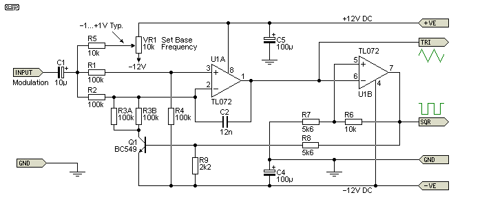
Figure 3 - Dual-Supply TL072 Opamp VCO Schematic
The VCO can be operated from a dual supply, and that only entails a few minor changes. However, there's not really a great deal of benefit to using a dual supply, as it doesn't simplify the circuit in any way. It does allow the modulating signal to be direct coupled, but that doesn't necessarily provide any advantages. It's important to connect the input stage (including the transistor) as shown. Frequency is 296Hz for this version with VR1 centred, and the modulation sensitivity is around 28Hz/V (positive or negative). Sensitivity is halved because the effective supply voltage has been doubled compared to the single supply version shown in Figure 2.
If Q1's emitter is connected to ground (commonly seen in schematics on the Net, but not recommended), the base-emitter junction can be reverse biased to the point of possible breakdown. This may seriously affect the transistor's performance. Using a ground reference for the input stage of a dual supply version also means that the modulating voltage (AC, DC or a combination of the two) must always be positive.
The output of U1A and U1B are (more or less) symmetrical around zero. The base frequency can be set by a pot as shown, and the modulation signal is symmetrical around zero volts. If the source circuit is direct coupled, it must be capable of providing some current. Despite appearances, the input will not be at zero volts when the pot is centred. The voltage will be around -1.3V and to obtain a linear frequency change with input the source must have a low impedance. The input can be supplied via an opamp buffer if desired, but for most applications it's not necessary.
If the modulation input is referred to ground (e.g. if DC coupled from another opamp) or clamped to ground, the base frequency will be increased to around 330Hz. The figure of 296Hz above applies only when the modulation signal is capacitively coupled as shown, and allows for the -1.3V DC offset.
For many applications, and especially for running frequency scans on speakers or crossover networks (or any filters for that matter), you usually need at least a reasonable approximation of a sinewave. The next circuit will do just that, but it's not a precision circuit. The output level (and distortion) will change with temperature. In most cases, this isn't a serious limitation, but expecting low distortion isn't an option - the best you can expect is around 1.5% THD (predominantly odd harmonics).
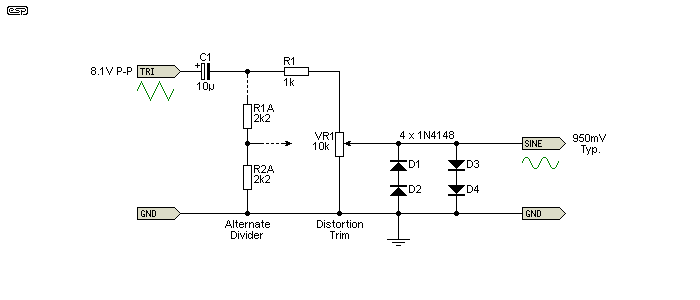
Figure 4 - Diode Sinewave Shaper
As shown, four diodes are used to clip the triangle wave in such a way as to get minimum distortion. VR1 is used to trim the distortion, but it's very unlikely that you'll be able to get the THD much below around 2% because the clipping circuit is greatly simplified. Many function generator ICs use an expanded version of the diode clipper to get better distortion (but with a far more complex circuit), but it's rarely much better than 0.5% despite the extra circuitry.
If you're not too worried about minimising distortion. just use a pair of 2.2k resistors (shown as 'Alternate Divider', R1A and R2A). The circuit as shown expects an input voltage of around 8V peak-peak, as will be obtained from the circuit shown in Figure 3. If you use the single supply version (Figure 2) you can feed the diode clipper via the 10µF cap and a single 1k resistor. Simply omit VR1, R1A and R2A, and connect R1 directly to the diodes.
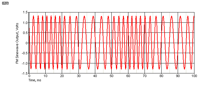
Figure 5 - Frequency Modulated Sinewave Output
Above is the waveform from the Figure 2 circuit, with VR1 centred and a 4V P-P (1.414V RMS) modulating signal at 20Hz. The diode clipper uses the four diodes fed via the 10µF cap and a 1k resistor. The frequency modulation is clearly visible, as is the wave shape. It's not a perfect sinewave by any means, but it's quite acceptable for frequency response scans. The base frequency (without modulation) is 292Hz, and we know from the data above that this circuit has a deviation of 55Hz/V. Therefore, the maximum frequency is 402Hz, and the minimum is 182Hz.
If you want to build any of the circuits shown, you'll need to use Veroboard or similar. No PCB is available, and it's not expected that there will ever be enough demand to warrant having boards made. The circuits aren't critical, but I do recommend that you use a 100nF ceramic capacitor as close as possible to the IC supply pins. This isn't needed for the LM358, but is required for many other opamps that are a great deal faster.
You will need to experiment a little to get the frequency you need. Use the values shown to get a general idea, and if the capacitance is doubled then frequency is halved (and vice versa of course). You can also change the resistors around the input stage (or the Schmitt trigger). Changing the Schmitt trigger resistors will change the output level of the triangle wave, which will affect the distortion when the diode clipper is used to obtain a sinewave. If lower resistances are used for the input section you may see waveform changes because the transistor may not be able to turn on hard enough to accommodate low values for R2 and R3A/B. R1 and R4 can be changed without affecting the frequency, but both must be the same value or the wave shape will be badly affected and the frequency will be changed. 1% resistors should be used for all input resistors (R1 ... R4).
If you build the VCO, you need to be aware that if you make an error, it's quite likely that you'll get no output at all. The output voltage may be stuck at zero or around 10V. If the triangle output is at zero, the square output will be at around 10V and vice versa. The circuit relies on feedback, and even a seemingly trivial error will stop it from working. The only thing you can do is to check all wiring very carefully, secure in the knowledge that if everything is wired exactly as shown, it will work.
 Main Index
Projects Index
Main Index
Projects Index