
|
| Elliott Sound Products | Project 142 |
This project is unashamedly based on Project 102 (Simple Pre-Regulator), but is intended to be used with relatively high current devices that don't need extremely good regulation. The pre-regulator was designed to allow the use the P05 supply module from a higher voltage source, but this version is intended to replace P05. It is not suitable for high-sensitivity preamps (p06, P66, etc.), but is ideal for (for example) P113 headphone amps - especially where several are used in a project.
This project is very simple, and can be wired on tag-strip or Veroboard. Regulation is quite acceptable, and ripple will typically be less than 1mV or so with an output current of up to 1.5A or so. The primary difference between this supply and P102 is that this unit uses Darlington transistors. Readers of my pages will know that I'm not a fan of these, but in this case they are ideal.
The regulator uses either TIP140/145 or TIP141/146 transistors (the 80V versions are somewhat easier to get), or other Darlington transistors such as BDW42 (NPN) and BDW47 (PNP) - these are shown in the schematic. The BDW42/47 are ON-Semi devices and are likely to be much cheaper than the TIP transistors. You can also use separate output and driver transistors if you wish, but this makes assembly more complex and won't be described here.
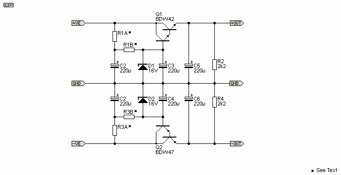
The circuit is shown in Figure 1 and it is fairly simple. You will need to make a few simple calculations to determine the resistor value, but this is explained below. This circuit is based on the 'enhanced' version of P102, hence the additional capacitors. The caps across the zener diodes can be omitted if your application isn't overly critical and doesn't mind a bit more ripple. At 2.1A output (6.8 ohm load at 14V), theoretical ripple will increase from about 600uV to a little over 1mV. Naturally, the output ripple also depends on the input ripple. For these examples, the RMS input ripple is assumed to be 500mV.

Figure 1 - Simple Regulator Schematic
The circuit shown uses the 16V zener diodes (D1 and D2) to regulate the output voltage to just under 15V. The voltage can be changed simply by using a different zener voltage and recalculating a few resistor values. The output voltage can be expected to be up to 2V lower than the zener voltage. Very few circuits will care if the supply rails are not exact, and most will not be affected in the slightest by voltage differences of as much as a couple of volts between the positive and negative supplies.
Using the suggested transistors will allow for input supply voltages up to ±42V quite safely, but they will need to be mounted on a heatsink (with insulating washers). If you have a supply voltage of more than 56V, use transistors with a higher voltage rating. Also, be vary careful of the maximum power dissipation rating for the transistors. If you have an input supply of (say) 35V and an output voltage of 15V nominal, the absolute maximum output current is 4.25A, but only if the transistor case temperature can be kept at 25°C or less! How did I arrive at that figure?
Device dissipation is based on the voltage across the transistor and the current through it. The BDW42/46 transistors are rated for 85W at a case temperature of 25°C, so ...
I = PD / V
I = 85W / ( VIN - VOUT )
I = 85 / ( 35 - 15 ) = 4.25A
It is clearly silly to expect that the case temperature can be maintained at or below 25°C, so I suggest that dissipation be kept below 30W. TO-220 transistors are notoriously difficult to keep cool because of the small mounting tab and a single screw at the wrong end. The mounting hole is actually as far away from the heat source as possible! Now you can do your own calculations, based on a maximum power dissipation of 30W. Make sure that you provide an adequate heatsink. Although the devices are rated for 30W dissipation with a case temperature of a little over 100°C, this is never recommended - I don't like the case temperature of any transistor to exceed ~75°C
For the example above, current is now limited to 1.5A (30W / 20V). If you need more current, reduce the input voltage. If the input voltage is reduced to 25V, then you can get 3A continuous current. For the types of things that might use this power supply, I would expect that 2A maximum will probably be enough. If you need more current and/or better regulation and ripple rejection, then this is not the power supply you need.
The next calculation is to determine the value for R1 and R3. First, measure the input supply voltage (V1). The resistor value is calculated to provide a nominal zener current of 15mA, and this will ensure sufficient base current for the Darlington pass transistors for far more current than you can draw without destroying the transistors.
V2 = V1 - VZ (Where V1 is input supply voltage, and a VZ is the zener voltage used)
R1 = R3 = V2 / IZ (R1 and R3 values are in kΩ, IZ is zener current in milliamps)
P = V2² / R1 (P is power dissipation of R1 and R3 in mW)
Let's assume an input voltage of ±25V and zener current of 15mA for an example calculation ...
V1 = 25V
V2 = 25 - VZ = 10V
R1A = R1B = R3A = R3B = 10 / 15 = 0.666k (use 660 ohms in total, 2 x 330 ohms)
P = 15mA² × 330 ohms = 75mW (use 0.25W)
The dissipation in Q1 and Q2 must be calculated as described above, and you need to know the current drawn by the external circuits. For example, if the external circuitry draws 1.5A, the transistor power dissipation is ...
P = V2 × IOUT = 10 × 1.5 = 15W
The input voltage is important. It must be high enough to ensure that the minimum input ripple voltage is still well above the regulated voltage. For example, if the supply voltage is only 20V and there's 5V peak-peak ripple, then the minimum voltage is about 17.5V. This is barely enough to allow the circuit to regulate, and output ripple will be much higher than expected. If you need supply voltages of ±15V (nominal) as shown, the transformer should be 20-0-20V AC, and the minimum capacitance after the rectifier needs to be 2,200uF (ripple ~6.8V P-P at 2A). I suggest that a more realistic minimum capacitance is 4,700uF for 2A output, giving a ripple voltage of ~3.25V P-P.
A 20-0-20V AC transformer will have an output voltage of 28V DC with no load, falling to around 24V DC at 2A output. This is ideal for an output of 15V. If you need a higher or lower output voltage, scale the input voltage accordingly.
Note that this circuit has no short-circuit protection, and will attempt to deliver the maximum possible current if shorted. This will almost certainly result in the failure of the output transistor(s). It's certainly possible to incorporate current limiting, but that rather defeats the intent of the project because it adds considerable complexity.
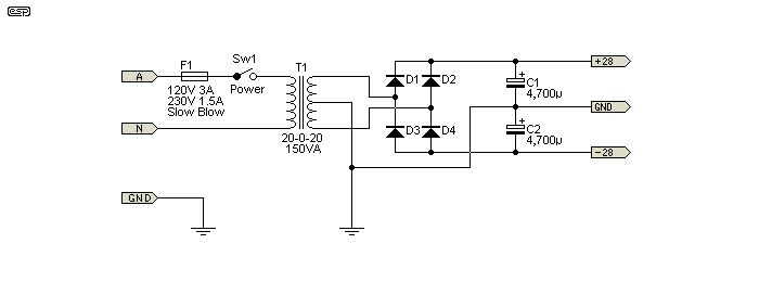
By far the simplest approach is to use fuses in the output. The circuit shown in Figure 2 is good for at least 2A, and if 3A fast blow fuses are used the transistors might survive a short. Instantaneous dissipation will be in the order of 160W with a shorted output, so the chances of survival aren't very good. This is always a major disadvantage of simple circuits - useful functions (like short-circuit protection) have to be omitted or the circuit isn't simple any more.
Transformer & Rectifier
There's nothing special or even very interesting about the transformer, rectifier and main filter, but it's included anyway for the sake of completeness. The design shown is intended for up to 1.8A each for the positive and negative supplies, and is essentially the same as the one I used for simulation testing of the supply.

Figure 2 - Transformer, Rectifier & Filter
While a 150VA transformer might seem like overkill, it's not. If the supply is operated at a continuous current of more than 1.8A you need a bigger transformer. For example, if the current is 2A, then the total rating is actually a little over 170VA (172VA to be exact) and the transformer would need to be somewhat larger - at least 200VA in fact. If the supply is used to power a small power amplifier or a (large) number of P113 headphone amps, then the average current should be less than 1.8A.
The size of the transformer depends on the load, as always. A simple and reasonably accurate way to determine the size needed is to multiply the AC voltage (across both secondaries) by the continuous average DC current then double it ...
VA = ACTOTAL × IDC × 2
VA = 40 × 1.8 × 2 = 144 VA
The value obtained is a little shy of the measured (simulated) figure, but will normally give a figure that's not too far off the mark. I leave it to the constructor to make a final determination, but it's far better to use a transformer that's too big than one that's too small. Any transformer operated at above its ratings continuously will fail.
Construction is non critical, and the resistors, zener and power transistors can be mounted on a tiny piece of Veroboard, tag-strip or similar. There are no stability issues, and you only need to make sure that the transistors have an adequate heatsink. This depends on the current drawn, whether it's continuous or intermittent, and (of course) the transistor dissipation.
For the examples given and assuming continuous operation at 1.8A, the heatsinks will need a thermal resistance of around 2°C/W each. This will be about right for a dissipation of 18W in each transistor and a temperature rise of 35°C (60°C maximum case temperature, and allowing for 1°C/W thermal resistance between the transistor case and heatsink). As always, there is no such thing as a heatsink that's too big, so feel free to use a larger heatsink than you think you'll need.
At low currents (less than 500mA), mounting to the chassis may be sufficient - provided it's made from aluminium no less than 2mm thick. Even a steel chassis will keep the temperature within limits at significantly lower currents, but if that's all you need you won't build this circuit anyway. Remember that the transistor cases must be electrically isolated from the chassis, and Sil-Pads will be fine due to the low dissipation.
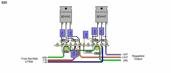
A suggestion for assembly is shown in Figure 3. This construction method will be quite acceptable for most applications. The earth (GND) terminal point should ideally be isolated from the heatsink to prevent earth loops.

Figure 3 - Construction Suggestion
The above example shows how you might assemble the supply using a length of tag-strip. The drawing is intended as a guide only - many of the parts have longer leads than you'd use in practice so I could show how each is wired. Because it's a guide, I don't suggest that you copy it as shown - the version shown was simply drawn up, and it's probable that I'd do it differently if I built the circuit myself.
As implied above, I have not built this circuit, mainly because I have no immediate need for it. If this causes you concern, fear not. Although I've not built this specific circuit, the general type is one that used to be extremely common. Before the advent of IC regulators, this was one of the most common arrangements where the powered circuits needed a fairly quiet (ripple-free) supply, but perfect regulation wasn't warranted or necessary. At various times, I have built a great many regulators that follow the general principles described, so I know they work.
Connect to a suitable power supply - remember that the supply earth (centre-tap, ground) must be connected! When powering up for the first time, use 10Ω 5W 'safety' resistors in series with each supply to limit the current if you have made a mistake in the wiring.
There is very little that can go wrong, but be very careful - wiring mistakes are easy to make with tag strips. Most faults you may find should be easily rectified because the circuit is so simple. Be especially careful not to short the outputs, either to earth (ground) or each other. This applies both while testing and in use.
 Main Index
 Projects Index