
|
|
| Elliott Sound Products | Project 134 |
Many of the most expensive measurement microphones available use a 4mA current loop interface, but don't expect any of them to supply any detailed information. They all describe the interface, but no schematics are available anywhere that I found, so I figured that it was high time this was rectified. The 4mA current loop power system is also known as "CCP" (constant current power - G.R.A.S.), ICP® (integrated circuit piezoelectric, PCB Piezotronics), IEPE, and CCLD, DeltaTron® (Brüel & Kjaer SVM A/S), ISOTRON® (Endevco Corporation), etc.
Accordingly, I have developed a mic preamp and a 4mA current source that work very nicely together, and the current source can also be used with professional measurement microphones from the likes of Larson Davis, BSWA, G.R.A.S., PCB Piezotronics, and anyone else who makes a standard 4mA current loop powered microphone preamp. The preamplifiers from the professional manufacturers generally do not include the microphone capsule, and the preamp plus capsule combination can be very expensive indeed (well over $2k in some cases).
Just because the microphone shown here uses the 4mA interface, this does not mean that it is automatically high quality (it uses a standard electret capsule, after all), and nor does it mean that very long cables can be used, however it should still be fine with as much as 22nF of parallel capacitance - that represents a fair cable length. In common with most microphones that use the 4mA current supply, the recommended connector is a BNC at the microphone and power supply ends, and standard double-ended BNC leads are used for interconnection. I have seen a claim that higher current (such as 6mA) provides a lower impedance, but please discard any such idea - that's just nonsense.
The proliferation of these microphones for professional noise measurement clearly shows that balanced connections are not needed for microphones and other stand-alone signal sources. A single core coaxial cable provides almost perfect rejection of noise for a microphone. This is not widely understood, but is true nonetheless. A low impedance microphone and coax cable can be used in the most demanding of situations, and noise pickup is rarely (if ever) a problem. This is well known in professional noise measurement circles, but not for pro-audio. The latter is actually a far less demanding role, and one where the recording will rarely be used as evidence in court.
There are any number of ways to make a current source, and hence there are also many different ways to design a 4mA power supply. One common approach is to use a junction FET, with a trimpot used to set the current. This is a perfectly good method, but finding suitable JFETs can be a real pain. Bipolar transistors are probably a better method, especially because it's possible to make the current independent of the active device. Noise is not really a problem, because any noise made by the power supply is absorbed by the mic preamp. Although the interface is referred to as a 4mA current loop, the actual current is not critical and does not normally affect the gain of the microphone and preamp.
A constant current source has an extremely high output impedance, so the preamp noise dominates. In reality, it ends up being the microphone itself that determines the noise floor, although for most general purpose measurement applications this is really academic. Even for recording, the microphone noise is usually swamped by the background noise of the recording environment unless it is particularly well insulated from outside noise.
The supply voltage is 24V, and this seems to be standard for these interfaces. The supply is always regulated, as this removes all traces of very low frequency noise (caused by mains voltage variations), hum and noise in general.
Figure 1 - Voltage Regulator, Sufficient For 10 Microphones
The voltage regulator is shown in Figure 1. This can power 10 microphones easily using the bipolar transistor current source shown below, or 20 mics if you use the FET version. This is fairly conservative (80mA total current draw), but conservative designs are more likely to survive than anything that's pushed to the limits. The mains input is either 230V 50Hz or 120V 60Hz, according to where you live. The mains switch and fuse has not been shown, but these are obviously required.
The transformer should have a 12V secondary, rated for at least 1A, but preferably a little more - up to 2A is fine. The regulator IC should be fitted with a heatsink - sufficient to keep its temperature below 40°C. All diodes should be 1N4004 or similar. Filter caps should be rated for 50V DC. Do not connect this power supply directly to a microphone unit - the mic must be connected via a constant current source as shown below.
The two different current source designs are shown below. Use the one that you prefer, bearing in mind that the JFET version must be adjusted, while the bipolar design does not. However, the BJT circuit draws double the current because it's a current mirror - Q2 mirrors the current drawn by Q1, so the two take 8mA ... 4mA each. Two alternative current sources are shown below, in Figure 3
Figure 2 - Current Sources, Bipolar Transistor and JFET
While both of these circuits perform well, I suggest that the 'dual transistor' current source shown in Figure 3 be used. The availability of once common FETs is poor, and seems to get worse as time goes on. Bipolar transistors have no such issues. Because of the relatively high single supply voltage and the large value coupling cap (essential to avoid low-frequency rolloff), significant protection is needed to ensure that following circuitry is not damaged. This can happen if a microphone lead is shorted, and will cause a -24V pulse with enough current to cause damage. The coupling cap must be rated for a minimum of 25V, and preferably more.
While these circuits both appear to be very simple, the output can be destructive if a microphone lead is shorted, especially with no mic attached. Without a mic connected, C1 (either circuit) will charge up to the full 24V. Should a mic input be shorted (and it will happen at some stage), C1 will force the output to -24V, and with plenty of current available. This will destroy the input of any opamp or digitiser that may be hooked up to the output unless the following circuit has heavy-duty input protection. The zener diodes limit the maximum possible positive or negative voltage swing to a little over 6V, and they pass the otherwise destructive voltage and current to earth (ground).
The 1N4148 diodes isolate each individual current source from the supply rail. Without them, when the power is removed the coupling capacitors will attempt to discharge back into the power supply by reverse biasing the current source. The diodes prevent this from happening, and must not be omitted.
The FETs are fairly critical. Other types may not be capable of supplying enough current, but the BF245C types shown are known to be capable of well over 4mA. You will need to know exactly what to look for if you decide to try something else. The bipolar transistors are shown as BC559, but can be replaced with almost any small signal PNP device that can withstand a collector-emitter voltage of 30V.
The current sources need to be checked and/or adjusted before use. A 1k resistor is a good test value, because even if the current source is shorted the maximum current is 24mA. Connect the resistor in series with your multimeter set to measure DC current. Verify that the current source (BJT or FET) is providing around 4mA, ±0.2mA. The exact current is not critical, but if you can adjust it to be exact, then there's no reason not to do so. The BJT version can be adjusted if you wish, by reducing R3 from 5.6k to 4.7k, and adding a 2k trimpot in series.
If the current is not 4mA and cannot be adjusted, check your wiring as you have made a mistake. If you use a FET other than the BF245C specified, it is entirely possible that you will not be able to obtain sufficient current. That particular FET was selected because it is reasonably common, inexpensive, and can deliver 4mA easily.
If you know what you are doing, there are several other current sources that will also work. However, you must resist the temptation to use a common reference voltage because there will be a certain amount of cross-coupling via the reference, and that will cause crosstalk. I was surprised at how much cross modulation I saw before I discovered the the two 1N4148 diodes for my two FET current sources were wired in parallel by mistake. Microphones often operate at sub-millivolt levels, and crosstalk will cause major problems.
You can also either of the 'traditional' BJT current sources instead of the current mirror, with version 'A' using a LED as the voltage reference. These alternative versions are shown below.
Figure 3 - Alternative Current Sources
Either of these sources will work well, with the dual transistor version being the preferred option of all those shown here. It has a higher output impedance than the LED referenced circuit, and is more dependable than the JFET. In reality, there's very little between them though, and of all the current sources, the current mirror shown in Figure 2 will have the best thermal stability - provided the two transistors are in excellent thermal contact. In reality, it doesn't really matter if the current drifts, provided the microphone circuit shown below is able to maintain a DC voltage that's greater than 5V and less than ~16V over the temperature range of interest. Note that any small signal BJTs (bipolar junction transistors) can be used in any of the transistor variations. All are PNP.
The microphone is a very simple circuit, and only adds a PNP transistor and two resistors to a standard electret capsule. The schematic is shown below, and is simply an emitter follower from the microphone's internal FET. You can expect to get a bit more gain than normal from the capsule though, because the feed resistor (R2) is effectively bootstrapped. This makes R2 appear to be greater than its 5.6k value. Don't get too excited - the effect is not great, but it does boost the output a little.
Figure 4 - Microphone Circuit, Using Common Electret Capsule
It may be necessary to adjust R2 to get somewhere between 5V and 12V at the output when the circuit is supplied with 4mA. The value can vary significantly, depending on the electret capsule used, but 5.6k is a good starting place and may work for many capsules. To increase the terminal voltage at the BNC connector, R2 must be reduced - this is the opposite of what you may expect. Further testing has shown that Panasonic WM-61A capsules need a resistance of about 1k. Alternatively, you can use a sub-miniature 10k trimpot in place of R2, and that allows you to set the DC voltage to around 10V. A few volts either way isn't a problem though, preferably erring on the low side (around 5-10V for example).
As you can see, the circuit is very simple. There are many possibilities for the casing, and the ones I used were turned on a lathe (see photo below). 12.7mm diameter aluminium solid round is ideal, but as always it depends on your abilities, tools and what you want your mic to look like. If you have the materials available (and the tools to work with it), stainless steel would look excellent. The output connector is a female BNC, and you will have to figure out a way to keep it inside your housing. For my first attempt, it's a force fit which works well because the threaded section is plastic.
It is extremely important that the case is connected to the shield of the cable. If you don't, your microphone will probably pick up lots of 50 or 60Hz hum and noise. The earth connection must be very secure, or you will get intermittent noises - they very worst kind because you know that you'll get noise when it will ruin a particularly important measurement. Metal BNC connectors can be held in place with 3mm grub-screws spaced at 90° angles. These will hold the connector in place and provide electrical contact.
Unlike the precision microphones referred to in the introduction, this circuit will not provide a nice reliable 10-12V at the output when supplied with 4mA. The voltage is largely dependent on the voltage across the FET inside the electret mic capsule, and may vary from around 4V up to 9V or more. The exact voltage doesn't matter a lot, provided the signal doesn't clip or distort at high sound pressure levels (SPL). Most electret mics are limited to about 120dB SPL (unweighted), although it's not usually a specified parameter.
The first of my test units gave an output of 67mV/Pascal (67mV at 94dB SPL), but was showing signs of distress at 114dB SPL, giving an output of 670mV RMS but with some visible distortion. The DC voltage at the mic output was 13V for the first and 12V for the second unit. The second unit gave 76mV at 94dB SPL, and again, there was distress at 114dB. This isn't a huge problem in most cases, as 114dB SPL is rather loud. This is not a mic for drum kits or placing in front of guitar amps - you'd use it for speaker measurements or recording quieter instruments.
There is never any requirement for extreme SPL when measuring a loudspeaker for example. It is actually rare that you'd even get to 1 Pascal (94dB SPL) - the vast majority of measurements are performed at no more than 1 Watt, and few hi-fi speakers will manage 94dB/W/m sensitivity. Where you will expect higher efficiency (compression drivers and horns for example), simply reduce the power to the driver under test, otherwise the noise will drive you nuts.
As shown below, I used a short length of 12.7mm aluminium rod that I drilled out and machined for the housing, and the circuitry is simply 'sky-hooked' together from the BNC connector. With so few parts, there is no reason to even contemplate a PCB. Take care soldering the leads to the transistor, because your connections may be much closer to the transistor case than normal, and you may overheat the junction. Be very careful to ensure that the transistor pins are all correct. Because there is no fixed reference (such as an outline on a PCB overlay), it's very easy to make a mistake.
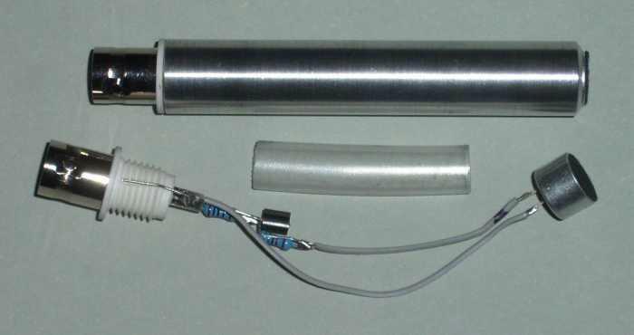
Figure 5 - Complete and Dismantled Microphone, Showing Internal Wiring
There are only a few connections, but each is important - take care, because the mic may be difficult to dismantle for repairs depending on your method of construction. The final circuit must be insulated so nothing can short to the case. A short length of heatshrink tube or some tape is all that's needed, as shown above it is removed for clarity. Don't worry too much about the component values - R2 can be adjusted if you wish, so that the mic has close to 12V at the output when connected to the constant current supply. The value of R1 is not critical - anything from 10 ohms up to perhaps 100 ohms will work.
Note the short piece of wire from the earth connection on the BNC that lies across the plastic threaded section. That is the connection from the shield to the case. Because I used a press fit for the connectors, the earth connection is very solid. It is possible to get it apart again though, by holding the BNC firmly and gently twisting and pulling the case. The mic capsule is also a press fit, but is not overly firm. It is held by some thin tape pressed into the mic body along with the capsule. Any excess is cut off with a sharp knife afterwards.
 | Note: Never connect the mic to a voltage source, such as a battery or regulated power supply - even for testing. It will only work when used with a constant current supply, and the circuit may be damaged if connected to a voltage source. For testing, it can be powered from a 9V battery (or other voltage source) with a 1k resistor in series. If you omit the resistor, Q1 will probably fail due to excess current. Performance is degraded if used with a resistor, however it will still work if everything has been done properly. |
Cables
You can buy ready made cables and they are often cheaper than making your own. However, you usually won't be able to re-terminate them when they fail because the connectors are crimped. You can replace the connectors of course, but it's essential that you get the right kind of cable. Since the connectors are BNC, you have to use the proper BNC connector and matching cable - some of them are not interchangeable.
For most applications RG58A/U is recommended. This is a robust 50 ohm coax, 4.9mm diameter, intended for LAN cables. It has a stranded inner conductor (19 x 0.0076mm) and a capacitance of 100pF/ metre. Make sure that you get the RG58A/U or RG58C/U - RG58U (without the 'A' or 'C') has a solid inner conductor that will break very quickly if used as part of a portable system. Almost all 75 ohm coax uses a solid centre conductor, so cannot be used.
If you need thin and unobtrusive cables, RG174/U is only 2.54mm outside diameter, but still has a good braided shield and multi-strand (7 x 0.16mm)inner conductor. At 102pF/ metre capacitance is such that typical lead length of 10 metres is just over 1nF, and well within the ability of the preamp.
Just because you have made 4mA current loop microphones and built your constant current power supply, this does not mean that your mics are just as good as dedicated (and perhaps very expensive) measurement mics. If you use good quality electret capsules you might come close though - some of them are better than you might think, but you can't rely on any claimed 'calibration certificate' unless it is individually plotted for the capsule. To get this normally requires that you spend far more than the $2 or so that you will pay for typical electret capsules.
If you have access to a sound level meter calibrator, you can use that to determine the reference output level. This can be reduced using a pot if you wished to do so, and you might want to adjust the pot so that 1 Pascal (94dB SPL) gives a reference output of exactly 50mV. From that, you can determine the level in dB from the voltage. For example, if you measure a loud noise at 450mV, the SPL must be ...
dB = 20 × log10 ( V2 / V1 )
dB = 20 × log10 ( 450 / 50 )
dB = 20 × log10 ( 9 ) = 19.1 dB
SPL = 94 + 19.1 dB = 113.1 dB SPL
This is what is done in a sound level meter. You have to accept the figures it gives, and unless you paid quite a bit for it the accuracy is suspect. You usually can't get access to the audio signal, and it's also nowhere near as useful as a good microphone (or several - these are so cheap to make that you can have as many as you like). You don't need to reduce the level if you don't want to - the calculation shown works with any voltages, but it may be more convenient to set an accurate reference level.
 Main Index
Projects Index
Main Index
Projects Index