
|
|
| Elliott Sound Products | Project 133 |
Projects actually don't get much simpler than this, but it's still a real problem for many people who want the sound from their PC or notebook computer to play through an installed PA system. If there is a commercial offering for this, I've not seen it. There are plenty of suggestions about how to record sound from the PA system onto a computer, and many of those are almost guaranteed to kill your soundcard.
Accordingly, the two circuits shown here can be used to play sound from the PC into a PA system, or record sound from the PA onto the computer. Both use a small, relatively cheap 600 ohm 1:1 transformer, of the type commonly called 'telephone' transformers. These are not known for excellent frequency response, but those I've experimented with are far better than you'd expect if driven properly.
It should come as no surprise that the basis of this project came from necessity - the clock club of which I'm a member needed to be able to play soundtracks and other audio over the existing church hall PA system. As is often the case, microphone inputs are comparatively plentiful, and these are the ideal for something like this.
The basis of this project is that it should be cheap and reliable, as well as easily built. No PCB is needed, as all wiring is easily done using point-to-point techniques. Everything can be held in place after testing is complete using hot-melt glue. In most cases, extreme fidelity is not needed, and very few small venues where something like this would be used will have a high fidelity PA system anyway.
 First, we need a transformer. The cheapest is to use a 600 ohm 1:1 telephone isolation tranny, as they are relatively low-cost and work well for the intended purpose. The goal is to make something that is reliable and functional, and hopefully cheap enough that it can be replaced easily if lost or stolen. Small halls that are hired for multiple reasons are extraordinarily difficult to monitor and control properly, and all relatively expensive items should be in a locked cupboard as a matter of course. Stuff still goes missing though, as I'm certain that anyone who has looked after such a system is well aware.
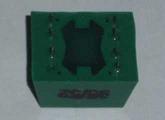
A photo of the transformer I used is shown on the left. Don't expect to get exactly the same type (these were specially made for a telecommunications project many years ago). However, similar transformers are made by countless suppliers and are far easier to get than was the case at the time. Some of those available will be better then the unit shown here.
The measured parameters of the transformer are given below. It's not hi-fi, but it actually quite typical of 600 ohm telephone isolation transformers. The source impedance for frequency response testing was 600 ohms, which makes distortion and frequency response worse than would be the case with a lower drive impedance.
| Parameter | Measurement |
| Frequency Response | 30Hz - >40kHz, -3dB |
| Maximum Level | 300mV at 30Hz |
| Distortion | 5% @ 30Hz |
| Primary Inductance | 3.64H @ 120Hz |
| Winding Resistance | 55 Ohms (Pri), 65 Ohms (Sec) |
The first circuit shown will suit most installations, where the system is in mono, because stereo is often worse than useless for small halls with inexperienced operators. There is a stereo version shown below though, if this is essential.
Figure 1 - PC to PA Mono Playback Interface
For the vast majority of cases, a 'telephone' transformer with a nominal impedance of 600 ohms and 1:1 turns ratio is more than suitable. If you do need a high fidelity system (mono or stereo), feel free to use a professional line transformer from the likes of Jensen or similar, but be warned that it will cost you a great deal more and be harder to get.
The pot may be log ("audio" taper) or linear, and that applies for all other circuits on this page. Personally, I prefer linear for this type of application, but you may disagree. Either way, the pot isn't there to give a nice smooth fader action - it's so you can reduce high levels or increase low levels quickly. All recorded audio material on a PC has to be treated with suspicion unless it has been carefully checked beforehand.
Figure 2 - PC to PA Stereo Playback Interface
Predictably, the stereo version is simply a duplication of the mono circuit, and is only useful if the PA system is stereo. You will need two mic inputs, with the Left channel panned full left on the PA's mixer, and the right channel panned full right. Bear in mind that if the soundtrack is in mono (very common, even with home videos), then the stereo interface will be no different from the mono version, except that one channel might be missing altogether unless the soundtrack was done properly. This is unlikely with many amateur productions.
The level control allows the person running the PC to adjust the level as needed. Videos and presentations can have extremely variable sound levels, and access to the software volume control is difficult and time-consuming while a presentation is in progress. Having a manual hardware control allows total control instantly, without the latency often encountered with software controls (assuming you can even get to them without disrupting the show.
The parts are not critical, but should be close to the suggested values. Actual performance will depend on the sound quality of the PC presentation more often than the hardware, but the transformer can limit overall fidelity. The source impedance is deliberately made as low as possible to maximise the transformer's performance. All transformers perform at their very best with a zero ohm source impedance, but this cannot be achieved with a passive unit such as this.
While it is certainly possible to add electronics, this adds complexity, and requires either and external power supply or phantom power. The latter may be available in some larger systems, but most will use a basic PA system that has no 'fancy' additions. This is especially true where the system is used by inexperienced people who may be barely capable of plugging in a microphone and getting it right.
Recording systems are common, and are generally arranged to take a line-output from the mixer and (ideally) use an external sound card to get the best performance possible. There are many different semi-professional and professional solutions available, for prices ranging from perhaps $150 or so. These commonly use USB or FireWire connections, some with S/PDIF connections as well (often both coaxial and optical). Wherever possible, use a line output from the PA system mixer, as the results will always be much better that way.
This is all terrific - but only if there is an available line output or an optical recording output from the mixer, and someone has the knowledge to use it properly. Commonly, the only thing that may be available is a speaker line, of unknown polarity and level. Speaker lines can be traditional 100V or 70V line systems, or might be 4 or 8 ohms. The amplifier power level is often not known at all, and the risk of destruction of your notebook PC's soundcard is very high if you get it wrong.
Accordingly, this process is not as straightforward as sending a signal to the PA system. That is very flexible, and mic inputs have enough gain to ensure that you'll get a good signal in all but the worst cases. In contrast, the PC has a limited input volume range, and if the level is too high it's easy to kill the mic or line inputs. Some notebook machines may only have a mono mic input with no provision for line inputs at all.
We have the likelihood of extremely wide level variations, and need to have excellent protection for the PC and other circuitry. Ideally we don't want to kill the PA system in the hall either. This makes a 'universal' interface difficult. Again, with some active electronics it's easy enough, but the circuitry becomes complex and you need an external power supply. The transformer is essential - that provides protection against ground loops and adds an essential level of protection to the PC's soundcard.

Figure 3 - PA to PC Mono Recording Interface
The above circuit will fulfill most needs, but there are changes needed to adapt it to the PA system being used. The lamp provides a degree of automatic volume control, which helps to ensure that the recording level is reasonable at all times. Clipping (input overload) and extremely low levels are both to be avoided, or the sound quality may be so poor as to be unusable.
R1 and R2 are the most important parts. If too small and connected to a powerful amp, they will burn out and may take the zener diodes with them. See below for some sizing recommendations. R3 can be a pot if you wish, and will give some additional control over the maximum level. If used, it should not be available to the operator - it should be preset to suit the PA system with which it is used. The two zeners are to limit the maximum possible signal level to something that may still cause the PC input stage to distort, but not enough level to damage the soundcard. The fuse (F1) simply prevents catastrophic failures from damaging the amplifier.
The suggested Lamp is a #327. This is a 28V lamp, rated at 40mA or thereabouts (1.12W on that basis). At full temperature, the filament will have a resistance of 700 ohms. These lamps are very common (mainly in the US) and are regularly specified for use in audio oscillators. In this application, the lamp allows the full signal level through at low input voltages, but the filament resistance increases rapidly as the voltage across the lamp increases, and this acts as a simple compressor to reduce variations in the output signal level.
| Power/ Voltage | Impedance | R1 | R2 |
| 100 W | 4 Ohms | 560 Ohms / 0.5W | #327 Lamp + 0 Ohms |
| 100 W | 8 Ohms | 680 Ohms / 0.5W | #327 Lamp + 0 Ohms |
| 200 W | 4 Ohms | 680 Ohms / 0.5W | #327 Lamp + 0 Ohms |
| 200 W | 8 Ohms | 1.0 k / 1W | #327 Lamp + 560 Ohms / 0.5W |
| 70 V | n/a | 1.8 k / 1W | #327 Lamp + 1.0 k / 1W |
| 100 V | n/a | 2.7 k / 2W | #327 Lamp + 1.8 k / 2W |
Some experimentation will be needed, because this is not an exact science by any means. In use, the PA system level may be set anywhere between deafening and just enough to give basic speech reinforcement. As a result, the PA system power or speaker line voltage can vary from maximum possible down to only a few volts. The values shown are designed to give an absolute maximum of 2V RMS across R3 as the PA system reaches clipping. This should be within the range of most soundcards, but yours might be different - especially if the only available input is designed for a microphone. If this is the case, reduce the value of R3, but remember that if the lamp is used, this will reduce the level further. In general, keep the level as low as practicable, but high enough to get a good signal to noise ratio in the recording. I suggest that the level be kept below ~250mV to prevent low frequency distortion from the transformer.
The suggested lamp will be most effective with power amps of around 100W, but it is easy to include one or more additional lamps for higher power systems, or those that use 70 or 100V lines. The design current through R3 at maximum power is 20mA, so the lamp's range is deliberately limited in the interests of prolonging the life of the lamp. Ideally, a circuit such as this should be able to run for 10 years or more without ever requiring attention. The one exception may be the level control pot, as this will wear out much earlier than anything else, especially with constant use.
Figure 4 - Lamp Signal Compression Vs. Applied Voltage
Figure 4 should not be used as gospel, but it gives a good indication of the typical variation of signal voltage across a 100 ohm resistor with a varying applied voltage. In this case, the lamp used was a 48V type, with a rated current of 20mA (2,400 ohms hot resistance). At low voltages, there is virtually no signal compression, but increasing voltage causes more and more level reduction. While this lamp is different from the one suggested, the overall behaviour will be virtually identical - but at different voltage and current levels of course. Compression can be expected to start where the voltage across the lamp is about 20% of the rated voltage - this is visible above. The graph allows you to get some idea of the likely performance of the lamp that you use with the PA system you will be monitoring.
The signal is typically compressed such that a 6dB input increase will create an increase of about 3.7dB. This is a low compression ratio, but is designed to smooth out the recording level to make it usable. As noted above, you will almost certainly need to experiment to get results that suit your particular setup. Once the tests are done, you will have a recording interface that should give good results over a wide range of signal levels.
There are so few parts that a PCB would be silly. Everything can easily be mounted to a small piece of prototype board. The playback interface is easy, because nothing gets even slightly warm. This means that everything can be held together with some hot-melt glue. I suggest that the pot be left free and clear of glue, because that may need to be replaced with extended usage.
The recording interface is a little trickier. The lamp and main limiting resistors (R1 and R2) may get quite warm at times, so they must be mounted in such a way as to prevent short circuits or mechanical failure of solder joints or component leads. Remember that this interface should only be used if you do not have access to a line output from the mixer.
There is nothing critical about either of the circuits, but you must ensure that there is no possibility that the primary and secondary circuitry can ever be shorted together. This is where the telephone transformers help, because they are made to have high isolation between windings. Above all, you must be prepared to experiment a little - particularly if you need the speaker-line recording Interface.
These circuits are deliberately very simple, so they can be built by anyone with basic knowledge and good soldering skills. None of the circuits makes any pretense at being hi-fi, but expect them to be better than all but the very best PA systems. There are countless applications, but I expect that the most common uses will be for very similar situations that created the initial design in the first place.
It was only after using it a couple of times that the need for a user-accessible volume/level control was essential. The level variations between three different presentations were extreme, and the silly noises that PCs so like to make when you do anything were close to deafening! Noise levels depend a lot on the PC and quality of mic preamps in the PA system, but in general should be well below audibility in all but the quietest of meetings.
Sound quality will always be much, much better than you can ever achieve by placing a mic next to the PC speaker(s), or placing a PC mic next to a PA speaker ... and yes, I've seen both methods used. So, if you ever have a need to play pre-recorded material from a PC over a PA system, or need to record the proceedings and only have access to a speaker line, you now have solutions that will work extremely well once properly set up for the PA and PC that will be used.
 Main Index
Projects Index
Main Index
Projects Index