
|
| Elliott Sound Products | Project 13 |
This is a design for a low noise microphone preamplifier, which is ideally suited to low impedance (600 Ohm nominal) microphones. One limitation is that it is not balanced, which is not a problem in a home recording environment, but may allow the mic lead (and case) to pick up noise with long cable runs or in a hostile environment.
As shown, it is not really suitable for professional work (although it has been used in a stage mixer with excellent results), but the addition of a 1:1 microphone transformer on the input will convert it into a balanced preamp with very high performance. In most cases, a good mic transformer will actually outperform active balancing circuits, because there is (or should be) no ground reference. The shield of the balanced cable must be earthed of course, but in my experience with live music and studio work, less noise is picked up if the internal wiring is floating.
It is most regrettable that good mic transformers are rather hard to come by, and are expensive. If you happen to have a suitable one in your junk box, give it a try with this circuit - I doubt that you will be disappointed with the result. I have used this circuit in Front-of-House, foldback (monitor) and studio mixers, and managed to obtain extremely good results - I still have a little 6 channel mixer (which I use only occasionally now) using this circuit, and have never been even slightly tempted to replace it with even the best of opamps (or Figure 3 for that matter).

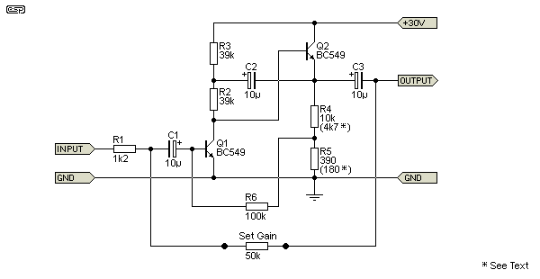
Figure 1 - Microphone Preamplifier
It requires a well regulated (or extremely well smoothed) supply voltage of 30V, and will typically be able to supply a maximum output level of around 7V RMS allowing for typical component spreads. With the component values shown, impedance matching is correct for a 600 Ohm mic, and the gain is about 40. Note that this is far too high to use with any microphone used for close-miked vocals or instrument amplifiers, but is suitable for normal speech.
By making the 'Set Gain' resistor a 50k linear pot, the gain can be varied from virtually 0 up to a maximum of 40 (32dB), with low noise and distortion at all settings. The output level from a well known brand of vocal mic has been measured at over 1 Volt peak-to-peak with loud singers, so the 'conventional wisdom' of mics having low output is clearly wrong. For this reason, making the preamp with variable gain is almost an essential requirement.
The open-loop gain of this little circuit is about 3,400 - this is obtained by disconnecting the feedback resistor, and bypassing R5 with a suitably large value capacitor. All this from a single amplifying transistor ! This is obtained due to the bootstrap circuit (R2, R3 and C2), which forces the voltage at both ends of R2 to be (almost) the same. That means that Q1 is operated from close to a perfectly constant current, which raises the gain and makes the transistor much more linear.
If the circuit is driving a following stage with an input impedance of around 22k, it is beneficial to reduce the value of R5 if the maximum possible output swing is needed. A value of 330 ohms biases the emitter of Q2 to about 19V, and this allows an output swing of ±10V into a 22k ohm load. The value of 390 ohms is optimum when driving higher impedances. (Note that the value of R5 has been revised from its previous value of 560 ohms.) The alternate values (4.7k and 180 ohms) can be used if you need to drive a lower than normal impedance.
Measurements taken when I was building lots of these show that the equivalent input noise was about -127dBm, so with a gain of 40dB, signal to noise ratio should be about 86dB relative to an output of 0dBu (775mV RMS). This translates to an equivalent input noise of about 3.2nV√Hz, or 446nV for a 20kHz bandwidth. This is completely unattainable in practice, because of the noise from the microphone itself as well as other extraneous noises which cannot be eliminated. These days it's easy to get lower noise, but when these were made in quantity (in the 1970s) it wasn't a bad effort for such a simple circuit. Even then, lower noise was certainly possible, but the circuit complexity and cost increased very quickly.
Needless to say, the use of metal film resistors is a must to get the best possible noise performance. The requirement for electrolytic capacitors does not compromise anything, and for the impedances involved relatively large value caps are a must. Use of Low Leakage electros may be worth the effort, but I have not experimented with this option. I have used solid 'tag' tantalum caps in this circuit, but they are (or were) revoltingly unreliable and I stopped using them after it was necessary to change every tantalum cap in a batch of about 20 small 8 channel stage mixers. I was not impressed!
This is a quiet preamplifier, but is only suited to low impedance inputs - the noise figure degrades rapidly as the input impedance is increased. The design - in particular the collector current for Q1 - was based on the noise / current / impedance graphs for the Philips version of the BC549 - minor variations are likely with different transistors, or BC549 devices from other manufacturers. Unfortunately, the grapg I used isn't included on most modern datasheets.
The entire circuit is naturally Class-A, and with a gain of 32dB, has an output impedance of less than 100 Ohms. The recommended load impedance is 22k or greater, so it is quite capable of driving a set of tone controls or a fader. Buffering with a good quality opamp will naturally reduce output impedance (and also increases output drive capability and open-loop gain) as shown in the example in Figure 3.
The exact same design has also been used as a virtual earth mixer for the mix bus in mixers from 6 to 24 channels. The only change is to remove the 1k2 resistor at the input, and connect the mix bus directly. The optimum impedance must be retained for low noise, so for a 10 channel mixer, each channel should have an output resistance of 12k to 20k to the bus. Fewer channels require lower resistance and vice versa.

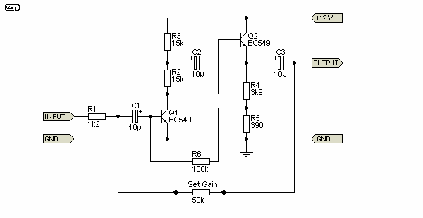
Figure 2 - 12V Version of Preamplifier
The Figure 1 circuit seems to discourage people because of the single +30V supply. Figure 2 shows the resistor values needed to run the preamp from a 12V or 15V supply, but naturally the output voltage is dramatically reduced before clipping. I have included this version to demonstrate that lower voltage operation is possible, as this seems to be something that people want. As shown, it will also work with a 15V supply, but the value of R5 can be reduced to 270 ohms to set the voltage at the emitter of Q2 close to 7.5V for maximum output level without asymmetrical clipping.
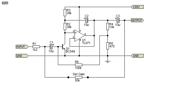
If you think it is worth the extra effort (which quite frankly I don't), the next version is interesting. The open loop gain of this configuration is now an astonishing 1,200,000 - or over 120dB from a single amplifying transistor. The opamp acts as a unity gain buffer - basically a 'high tech' version of the emitter follower in the previous circuit.

Figure 3 - Modified Version of The Mic Preamp
Although open loop gain, as well as output impedance and output drive capability are all improved, the noise figure can be expected to be slightly worse. Gain with the values shown remains at 32dB, and the opamp should be powered from the +30V and 0V rails (i.e. NOT with a split supply - the voltage will be too high for the opamp). This version has not actually been built and used in earnest, but has been simulated and is a viable proposition - it can be expected to work as described without problems.
 Main Index
 Projects Index