

|
| Elliott Sound Products | Project 112 |
 Please Note: PCBs are available for the latest revision of this project. Click the image for details, or select P93 or P88.
"Alas Poor Yorick ..." Well, there's not a lot of alas in this - indeed a lack of alas, one might say. Yorick just happens to be the name I chose for my dummy head recording microphone for reasons that shall remain obscure  Using a pair of P93 electret microphone amps, this dummy head can be phantom powered or you can use batteries. It will run happily on a standard 9V alkaline battery.
Speaking of Shakespeare, something that is not at all well understood is this snippet ... While writing 'King Richard III', poor Bill's word processor had a hard drive failure, and the actual quote (lament, more like it) was "Now is the winter of our disk content." - having just lost everything, I know how he must have felt. This was utterly misconstrued over the years, until we now have the mangled version that everyone seems to think is correct. Of course this is true- would I lie? To you ?
The project came about when I came across a polystyrene foam wig holder (replete with wig), and its final use was sealed on the spot. It still took me a year to get around to it, but hey, these things take time. With the addition of a pair of electret mics and a couple of RCA sockets, the dummy head was complete, just needing a suitable mic amplifier to finish it off. P93 was an immediate candidate, although for my application I used P88.
More than anything else, this is intended to be a fun project. While those who are especially interested in making recordings of <insert favourite application here> will find it very useful, the project also shows how powerful our auditory processing really is. To be able to listen to a recording made in natural surroundings with almost no reverb - which we normally do not hear in most rooms, even though it's there all the time - is remarkable. To hear the difference, simply mono the signal, and suddenly the reverb and general background noise becomes most intrusive.


Figures 1 & 2 - The Completed Dummy Head Recording System, Front and Rear Views
The completed dummy head unit is shown above. The details are given below. He's not particularly handsome by any stretch of the imagination, but that's not really a requirement for the application. The control box is shown below.
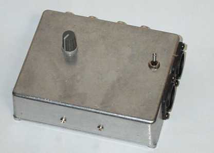
Figure 3 - Prototype Control Box
The prototype shown is based on the Project 88 hi-fi preamp (details shown below). It can run from a pair of 9V batteries, or an external DC source may be used. Any external supply needs to be (electrically) very quiet. Any hum or noise from the supply will have some impact on overall noise performance. I used NE5532 opamps in mine, but be aware that these (as well as many other high quality audio opamps) draw considerable current - around 20mA in total for two dual opamps. This means that battery life is fairly limited. Expect no more than about 10 hours continuous operation from alkaline batteries, less from zinc-carbon or re-chargeable types. As you can see, I added a pair of XLR connectors for flexibility, but this is completely optional.
There's not really very much to it. Simply take a suitable head such as the one shown, and make a couple of ear holes using a long, thin screwdriver as a boring tool. These should be located in approximately the position of real ear holes, but if you plan to add a wig for added realism (oh, really?) then make sure the wig doesn't cover the holes. The outer ends of the holes need to be enlarged so the mic inserts are a snug fit.

Figure 4 - Side View (Sans Wig) Showing Microphone Insert
Most of the expanded polystyrene foam heads are reasonably solid, and have a hollowed out section up the inside. This allows us to run the cables through easily. A rotary tool is useful for making neat cut-outs for the microphone connectors, and for enlarging the ear holes to accept the inserts. Overall insulation is not needed because polystyrene is an excellent insulator, so you only have to make sure that the mic leads (inner cable and shield) can't short together.
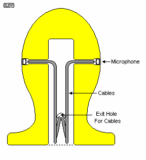
Figure 5 - Wiring Inside the Dummy Head
Getting the cables through the small holes from the mic locations, down the hollow centre and out through the opening for the connectors can be a challenge. You may find it easier to use a thin draw-wire that can be fed through the holes and hooked out with a stiff wire hook. Ultimately, I have to leave that part to you, as the best method will depend on what you have available. Because the hollow section is a reasonable size (at least in the heads I've seen), you have plenty of room to stash any excess cable.
Mounting the mic connectors may be easy or hard, depending on the connectors you have, and what you can find in your junk box. In my case, I have a large bag of the RCA connectors you see in the photos above, and it was possible to just screw them directly into the polystyrene. No, this is not the most secure fastening, but I don't plan to hang heavy cables from them, and tests so far seem to indicate that they'll be fine for as long as I need. Some care is needed, but that's not an issue.
I do recommend that the two connectors are electrically isolated from each other. Because of the small signal level, a ground loop will be created if the leads join at more than one place, and this will create hum. If you plan on gluing anything, remember that solvent glues will dissolve polystyrene foam (it just vanishes!), so only use adhesives that are designed for such applications (I don't actually know of any, which is why I tried the screws). PVA wood glue will work and does not dissolve polystyrene, but it probably won't bond very well either. The connectors could be attached to a strip of plastic and attached with cable ties. There are many possibilities, so see what works best for you.
There are actually two equally valid possibilities for the control box. As mentioned above, the P93 mic amp is ideally suited, and for reference this is shown below.
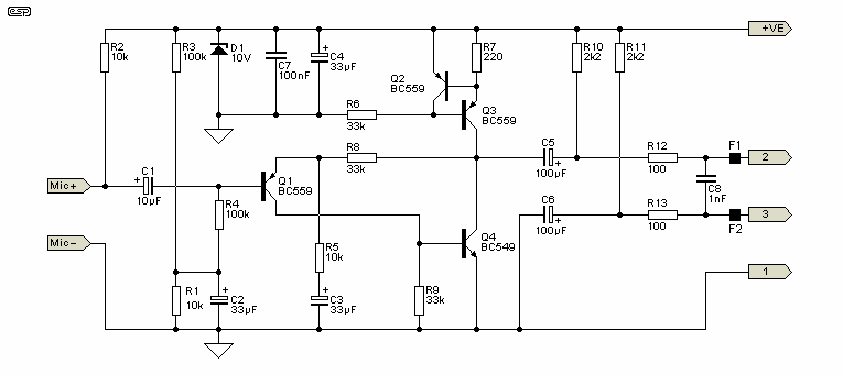
Figure 6 - P93 Microphone Amplifier
This is unchanged from the original project. The only difference is that the P93 board is not installed close to the mic capsules. Although it would be possible to do so, having XLR connectors on the dummy head would mean a substantial mounting because of the force needed to connect and disconnect. RCA connectors require very little force, making mounting easier.
Another method is to use the P88 preamp, and this is ideal if you don't need the balanced output and phantom feed capability. The gain needs to be increased, but it is a very flexible alternative.
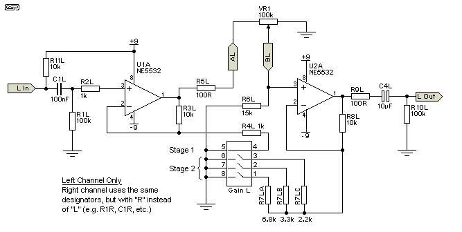
Figure 7 - Modified P88 Preamp as Mic Amplifier
The use of low noise opamps is highly recommended, but be warned that devices like the OPA2134 and NE5532 draw about 5mA per opamp (20mA per package for dual opamps), so you will be looking at close to 20mA for the amp. While 9V batteries can supply this easily enough, you will only get about 10 hours of use from a set. TL072s will give much longer battery life, but at the expense of noise.
As shown, the first stage gain is increased to 11, so a typical 20mV signal level will give you 220mV across the level pot. The gain of the second stage is also increased, and like the P88 can be made switchable to accommodate different recording systems. With the values shown, you can get the following ...
| Switch | Stage 2 Gain | Total Gain | dB (Total) |
|---|---|---|---|
| 1 | 2.47 | 27 | 29 |
| 2 | 4.03 | 44 | 33 |
| 3 | 5.54 | 61 | 36 |
| 2+3 | 8.57 | 94 | 39 |
| 1+2+3 | 10.05 | 110 | 41 |
The above is with the volume control at maximum. Switch #4 should be closed at all times for this application. You can experiment with the resistor values if you need more or less gain. The level control (VR1) can be a stereo (dual gang) pot, since in most cases you will not need to adjust the levels independently. Remember that the opamps are DC coupled, so expect to get some DC offset at the output pins. A 10µF bipolar cap may be used from the AL (and AR) terminals leading to the pot. This will prevent DC induced pot noise as the level is adjusted.
Note that R11 is not provided for on the PCB, but it is an easy matter to add it. Details will be included shortly in the P88 construction guide to make it a simple matter to adapt the preamp.
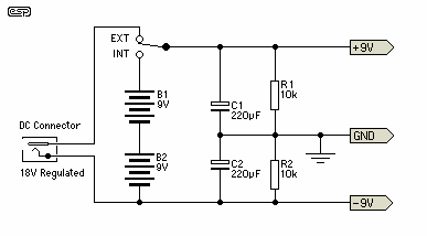
Figure 8 - Battery/ External Supply Wiring
The above is a suggested wiring scheme for the supply for the modified P88 board. While the battery centre tap could be earthed, then you would need a double pole switch to change from battery to external power. Feel free to do so if it makes you feel any better.
The supply will not be completely symmetrical because of the mic feed resistor. You can change R2 in the supply above to 5.6k or thereabouts to make the supplies equal, but the opamps don't really care that much.
Connect to a suitable power supply - remember that the supply earth (ground) must be connected! When powering up for the first time, use 100 ohm safety resistors in series with each supply to limit the current if you have made a mistake in the wiring. Refer to the individual project pages (P88 or P93, depending on which you used) for full test procedures.
Once the preamps are working, connect the complete recorder system to a tape machine or a computer sound card (via a mixer in most cases). It is quite uncanny to listen to the normal sounds around you via headphones from the dummy head.
 Main Index
 Projects Index