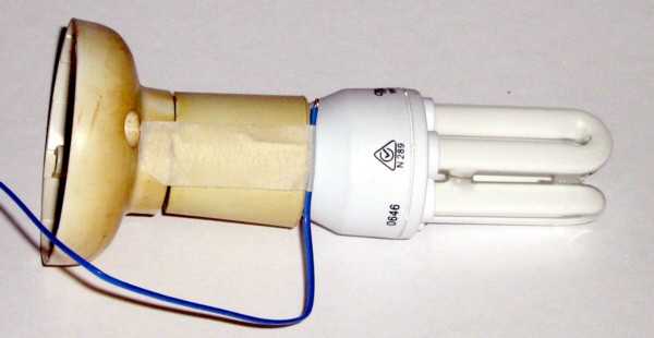
Figure 4 - CFL in Socket, With Thermocouple Attached
| Elliott Sound Products | Sealed Luminaire Test |
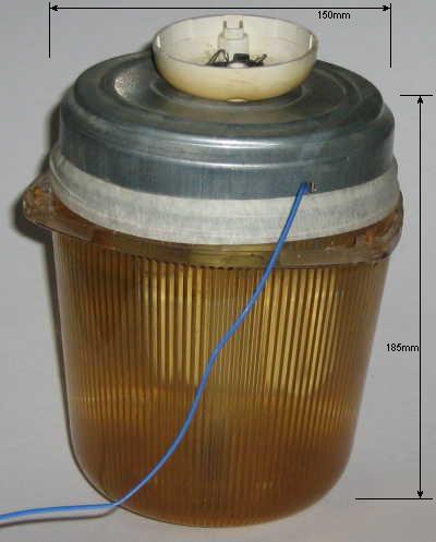
Because I didn't have a stray light fitting I could use for the test, I fabricated a test jig that would at least show the problem first hand. I ran two versions of the test simultaneously, using two temperature sensors. The temperature was measured at 10 minute intervals. The main test had the CFL set up as shown below, with a bead thermocouple taped to the lamp socket. This was installed in a housing, as shown further down. The second set of test results were obtained with a probe thermocouple that was used to measure the air temperature inside the test fitting, with the very tip of the probe just touching the metal top cover. The probe was inserted into the hole where the bead thermocouple lead exits the housing.

Figure 4 - CFL in Socket, With Thermocouple Attached
The housing is the lens from an outdoor fitting, but the base section is still attached to the house, so I had to find another. Using metal gives an optimistic final figure because it can conduct some of the heat to the outside air, but most fully plastic fittings (or a fitting attached to the ceiling) will give higher final temperatures than I achieved.
Likewise, the fitting is much larger than most, and the CFL somewhat smaller (lower power). A higher power CFL in a smaller enclosure will get a great deal hotter. I conducted the test in my workshop, where the ambient temperature was measured at 23°C at the beginning of the test, and the test fixture was just above floor level.

Figure 5 - Complete Test Fixture
The approximate dimensions are shown. The housing shown contains about 3 litres of air, and the lamp socket just sits in the hole at the top (it is not airtight). Before the test, I ensured that the CFL was at ambient (room) temperature. Remember that this is a highly optimistic test - not too many CFLs are operated in such a large sealed enclosure with a metal top, and a rather tiny 10W lamp as the test subject.
| Time | Temperature (°C) | |
| (minutes) | Bead | Probe |
| 0 | 23 | 23 |
| 10 | 48 | 34 |
| 20 | 55 | 39 |
| 30 | 58 | 40 |
| 40 | 58 | 42 |
According to countless Q&A sites, it would be considered perfectly alright to install a 23W CFL in this enclosure, yet the test shows quite clearly that even a 10W unit will reach or exceed the typical maximum ambient temperature of 50°C in just over 10 minutes (based on the bead thermocouple). Even the highly optimistic figures here show that with an electrical power dissipation of only 9W (assuming a generous 10% overall efficiency) is enough to cause a significant reduction in the life of the electronics. Imagine a 23W unit - now dissipating over 20W as heat - in the same enclosure. It will get a great deal hotter, and even the optimistic probe thermocouple will indicate that the maximum ambient temperature is easily exceeded.
Further tests show that the internal temperature will typically be 20-25°C higher than the external (ambient) temperature, so for a recommended maximum ambient of 50°C the internals will be at around 70-75°C. This just qualifies as a safe operating temperature, and the electronic components will probably survive for the claimed life - remember that only 50% of lamps need to survive for the full rated life - the remainder will have died already.
The original fitting that the lens was from was rated for a 100W incandescent lamp. The heat won't cause the incandescent any problems, although as you can see, the lens has discoloured quite badly from when it was installed (it's supposed to be clear). In case you were wondering, the lens was removed because it had discoloured enough to reduce the light output noticeably - the original incandescent lamp is still installed, but without the cover (it's been there for over 10 years !).
This test is not especially rigorous, and it was only ever designed to give me an idea of how much power can be dissipated in a small enclosure without exceeding the maximum permissible ambient temperature. It is important that the reader understands that in the context of all electronics circuitry, the ambient temperature is that measured in close proximity to the electronics - it does not mean the ambient temperature in the room. If electronic circuitry heats up its own immediate environment, then that is the ambient temperature that the individual components experience.
The temperature inside the plastic housing of the CFL's electronics will be 20-25°C higher than measured by either probe or bead. A higher power CFL in a smaller (or even the same size) housing that is completely airtight (as required for outdoor use) will get far hotter (and faster) than shown in the table. Any claims that less than 50% of existing light fittings are suitable for use with CFLs is completely justified on the basis of this test. Based on looking at available fittings as of early 2013, I expect the claims are very optimistic, and I'd be surprised if even 30% of fittings are suitable. For outdoor fittings, make that 1% - virtually none!