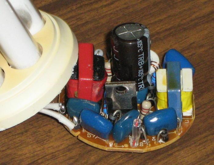
Figure 1 - CFL Internal Components
| Elliott Sound Products | CFL Intestines (with PFC) |
This photo shows the internals of a power factor corrected CFL. While the PFC circuit is fairly crude (it's just an inductor), it reduces the big current spike to something that looks a bit more like a sinewave. Rather than use a fusible resistor, this circuit is fused using a tiny glass PCB mount glass fuse. This is a much safer option, but still cannot protect the lamp from everything that could happen to it (by way of component failures).

Figure 1 - CFL Internal Components
The fuse is the small glass tube right at the very front of the PCB. I thought at first it may have been a thermistor, but the resistance is almost zero, indicating a fuse. The blue and yellow inductor is the PFC choke. For reasonable performance, it needs to be around 500mH to 1 Henry at 50Hz. The rest of the circuit is fairly traditional, the larger inductor (the big red one) is used to limit tube current, and there is a tiny transformer to provide transistor base drive at the back. Part of the latter can just be seen to the right of the electrolytic capacitor (white coloured toroid, with enamelled wire). The electrolytic capacitor is 10uF 400V, and is a 105°C type. The blue capacitors you can see are all rated at 400V - whether AC or DC is not stated. The PCB material is the cheapest you can get - it's a phenolic resin, which usually has paper reinforcement. The transistors are marked DK55, but no data could be located for them.
The lamp in question has seen somewhere between 200 and 500 hours of service, and is already noticeably dimmer than it should be. The area around the tube heaters is blackened (not visible in the photo), as is typical of a fluorescent lamp that it nearing end of life. The dark spot you can see in the top right of the photo is the transverse tube that joins the lamp sections, not a cathode black spot.
The lamp itself is a "Reliance" brand, and is rated at 20W. I don't recall when I bought it, I but haven't seen this brand on sale lately, so it seems to be one of the many marketing fatalities that have befallen CFLs in the last few years.
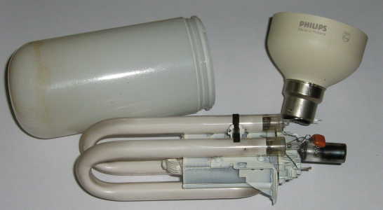
Figure 2 is the insides of an old CFL - typical of when they were first released (and yes, I did get a couple way back then - now I know why I kept this one after it became rather dim many years ago). At 475g, it is massively heavier than its incandescent equivalent. It was a long time ago, but as I recall, this lamp didn't last anywhere near as long as was claimed.

Figure 2 - Old Style CFL
The only technology involved here is how to cram a conventional fluorescent light into a small enough housing to warrant the term 'compact'. The circuit is identical to that of a conventional (straight tube) fluorescent lamp. You can see the ballast choke (inductor) and the starter unit in the photo. The ballast is a very neat fit between the bends of the glass tube, and is rigidly secured with a fairly heavy gauge steel plate that hooks onto the edge of the glass outer envelope.