
|
| Elliott Sound Products | ESR - Equivalent Series Resistance |
 Main Index Articles Index Main Index Articles Index |
ESR (equivalent series resistance) is a measure of the state of an electrolytic capacitor. All caps have ESR, but in the case of film caps it's generally too low to measure easily. As an electrolytic cap ages, the first sign of trouble is a rise in ESR. The capacitance value may be unchanged, but a higher than normal ESR is a sure sign that the cap is on the way out.
The ESR of an electrolytic cap is not a fixed value for a given capacitance. It falls as temperature is increased, and depends on many factors. Low ESR caps use a 'special' electrolyte to provide lower resistance, but it also varies by manufacturer, physical size and age. The 'typical' values shown in Table 5.1 (further below) are reasonable expectations for standard electros. In general, you should not measure anything higher than shown, but there will be exceptions where perfectly good caps measure a little more than indicated in the table.
Most people will buy a dedicated ESR meter, and this is the easiest way to get one that performs as expected. If you wanted to, you can build one easily enough, using a couple of opamps and not a great deal more. However, while this sounds easy, the reality is different because most opamps aren't fast enough. The general idea is that a 100kHz current waveform of known value (say 10mA) is impressed across the capacitor under test, and the RMS voltage across it is a scaled representation of the ESR. Most ESR meter projects use a microcontroller/ PIC with a few discrete parts, and these can give good results. Those using opamps will almost certainly be disappointing.
If 10mA gives a reading of 16mV, then the ESR is determined by Ohm's law - 1.6Ω. Unfortunately, few (if any) low-cost opamps are fast enough to provide a decent squarewave at 100kHz. Using something 'exotic' is unrealistic due to cost. The AD8397 would likely be fine, but they are SMD only and cost around AU$12.00 each (for a dual opamp). If you used a pair of those, you're probably half-way to the cost of a ready-made ESR tester.
Almost all commercial ESR meters use a digital approach, with a microcontroller generating a short pulse and measuring the instantaneous voltage, or using a more 'computerised' approach. You can use a signal generator and scope to take the measurement, but it's a rather cumbersome and time-consuming procedure. It also becomes problematic to measure very low ESR, as the voltage produced using a 'sensible' current is so low. For example, with a 10mA test current you'll measure only 500μV if the ESR is 0.05Ω. An ESR meter should be able to measure to below 0.1Ω. A 10mΩ (0.01Ω) resolution is not uncommon, so ESR can be measured with acceptable resolution down to around 30mΩ (0.03Ω).
If you have an ESR meter it can also be used to measure low-value resistors, but the resolution is not good enough to measure a 10mΩ shunt (for example). For values of 0.1Ω and above they are 'good enough' if you have low expectations. Some are better than others, but be aware that these are generally not considered precision instruments. Of course you can get high precision, but the cost is well beyond what most hobbyists will be prepared to pay.
Note that if you use a multimeter, you must verify that it can measure up to 100kHz, and it must be 'true RMS'. An ordinary (average reading, RMS calibrated) meter will give a wildly inaccurate reading with a squarewave, and it will be worse if you try to measure low-value caps. You can use a sinewave for testing, but the reading will be inaccurate if the capacitive reactance is more than 1/10th of the expected ESR. Most multimeters cannot provide an accurate reading above perhaps 10kHz, but sometimes much lower.
Like all components, capacitors are imperfect. This doesn't mean that the imperfections are audible (despite innumerable claims to the contrary), but it's still important to understand that a capacitor always has some resistance, some leakage and some inductance. The latter is determined by the physical length of the component and its leads, so short leads mean lower inductance with any cap. Leakage is easily measured in some caps, and almost impossible with others. The subject of this article is ESR - the other parameters are usually of little importance at low frequencies (i.e. audio).
The RDF and CDF parameters determine the Q of a cap with low ESR, otherwise ESR is dominant. Dielectric absorption (DA) is a direct result of dissipation factor, and can be seen (with some caps) as the voltage across the cap increasing after it's been discharged. It's very noticeable with electros, but much less so with film caps. It's still there, but is almost impossible to measure. Contrary to one claim I saw (and yes, this was actually stated), DA does not cause a problem similar to reverberation! In audio frequency circuits the effect is almost impossible to detect by any means in a blind test. Even with the extraordinary precision available from a simulator, the effect is so small that it can be ignored.
So, while all these 'faults' are real, they will never cause a problem with any capacitor used sensibly. In this case, 'sensible' means not using electros (of any construction) in filters, and ensuring that the DF doesn't cause excess dissipation in high-frequency circuits (e.g. RF, SMPS, etc.). If a capacitor gets hot during normal operation, you've used the wrong type for that application. That doesn't mean that a cap intended for RF circuits is 'better' than more common polyester/ Mylar/ PET or polypropylene caps. Knowing how to select a cap for an application depends on the application itself, and there are no simple guidelines. The interactions can be quite complex, so you need knowledge, not a table that says "for this, use this cap".
An SMPS with high ESR caps may fail to start normally, or it may fail unexpectedly. An old CRT TV screen may show a distorted image, because the high ESR changes the deflection waveform. Even LCD TVs/ monitors may show flicker, or a modulated screen brightness. As with an SMPS, high ESR can lead to premature diode and transistor/ IC failures. In audio circuits you may get excessive hum, or the output power may be severely limited before the output clips (see Fig. 4.1 for 'typical' supply rail waveforms).
These and many more issues are often created by capacitors that show normal capacitance, but a high ESR. This cannot be detected with a capacitance meter and can only be measured using an ESR meter or with a discrete circuit set up for the measurement. The ESR may not be a 'real' resistor in the physical sense, but it dissipates power like any other resistor. This causes the capacitor to get hotter than normal, ultimately resulting in the electrolyte boiling and the capacitor 'vents' - hopefully via the safety release, but often the entire capacitor is blown apart.
ESR can only be detected when an alternating current is connected to a capacitor, or when the capacitor is being charged and discharged continuously (in a power supply for example).
This can be seen as the capacitor's total in-phase AC resistance (impedance), combined with the DC resistance of the capacitor leads, the resistance of the interconnections to the plates, along with the capacitor's dielectric and the plate resistance of the capacitor (the latter is normally very low due to the way caps are constructed).
All the elements that create ESR can be simplified to a resistor in series with the capacitor. This resistor doesn't exist as a physical entity, so a simple measurement across the 'ESR resistor' is not feasible. ESR meters use an approach that helps to correct the results of capacitive reactance, and assuming that all resistances are in phase, the ESR can be determined by using the most basic electronics formula - R = V / I.
Just as important is P = V² × R, where 'V' is the RMS voltage across the capacitor and 'R' is the ESR. If there's a ripple voltage of 100mV RMS and the cap has an ESR of 100mΩ the power dissipated is 100mW. Should the ESR rise to 1Ω, the ripple voltage will rise to 1V (circuit topology allowing) and the dissipation will rise to 1W. Given the size of a 220μF 25V cap (for example), a continuous dissipation of 1W will cause significant heating. As the ESR rises, so does the dissipation and the capacitor's temperature. This becomes a vicious circle, as higher temperature will cause the ESR to rise over time, causing higher dissipation and temperature, etc. Even though ESR falls with increased temperature - it doesn't fall far enough to minimise self-heating.
The result is entirely predictable, and is the cause of countless equipment failures. This is often exacerbated by designers placing electros close to heatsinks, high-power resistors, etc. The characteristic bulging top of a failing capacitor is not always a reliable indicator. Certainly, once the top has started to bulge you know the cap is on the way out, but it may be very ill well before that happens.
Many ESR meters show typical values for various caps on the panel. These are generally reasonable, but there will be variations. A much lower than expected ESR may not be good though, as the cap may be shorted. The accuracy of the measurement is not overly important, because if you test few caps with the same value and voltage and get similar readings, then the exact figure is relatively unimportant. If you want to know the exact value, then you'll need to use a function generator and a scope to get a reading. The advantage of this is that you may be able to use a higher frequency allowing tests on smaller values. If your oscillator/ function generator allows it, you can use 1MHz or higher if you wish. You will need to make sure that the voltage measurement is taken directly at the capacitor terminals or lead inductance will mess up your measurement badly.
| µF / V | 10 V | 16 V | 25 V | 35 V | 63 V | 160 V | 250 V |
| 1.0 | 5.0 | 4.0 | 6.0 | 10 | 20 | ||
| 2.2 | 2.5 | 3.0 | 4.0 | 9.0 | 14 | ||
| 4.7 | 2.5 | 2.0 | 2.0 | 6.0 | 5.0 | ||
| 10 | 1.6 | 1.5 | 1.7 | 2.0 | 3.0 | 6.0 | |
| 22 | 5.0 | 3.0 | 2.0 | 1.0 | 0.8 | 1.6 | 3.0 |
| 47 | 3.0 | 2.0 | 1.0 | 1.0 | 0.6 | 1.0 | 2.0 |
| 100 | 0.9 | 0.7 | 0.5 | 0.5 | 0.3 | 0.5 | 1.0 |
| 220 | 0.3 | 0.4 | 0.4 | 0.2 | 0.15 | 0.25 | 0.5 |
| 470 | 0.25 | 0.2 | 0.12 | 0.1 | 0.1 | 0.2 | 0.3 |
| 1k0 | 0.1 | 0.1 | 0.1 | 0.04 | 0.04 | 0.15 | |
| 4k7 | 0.06 | 0.05 | 0.05 | 0.05 | 0.05 | ||
| 10k | 0.04 | 0.03 | 0.03 | 0.03 |
The table above shows the worst case ESR for new (standard, not low ESR) electrolytics for a range of capacitor values and voltages. If any cap with the value/ voltage shown has a measured ESR significantly exceeding that in the table, it is on the way out and should be replaced. The table was compiled using the details printed on my ESR meters, and is representative - some new caps will be much better than shown, some may not be quite as good, and ultimately you need to use your own judgement as to whether the measured ESR will cause a problem or not.
You'll see that for low and high voltage caps, the ESR is higher than for 'midrange' voltages. Around 35-63V is the happy area. High value caps have lower ESR than lower values as you'd expect. The datasheets for high value caps almost always show the maximum allowable ripple current. This can (and often is) exceeded briefly in normal operation, but provided it's not continuous that's usually alright.
One place where you can often see the effect of ESR is when a power supply electro has developed high ESR. Instead of seeing the normal sawtooth waveform, it can look like that shown below. The red trace is a normal 10mF electro with a 10Ω load and an ESR of 50mΩ. The cap is supplied from a transformer and bridge rectifier. The ripple is 1.12V RMS. If you measure the voltage with a multimeter, you'll see that the average doesn't change much, from 29.8V down to 26.8V. However, the amp will start clipping much earlier than normal, because it's the minimum voltage (<24V) that causes the problem. With low ESR, the minimum voltage is ~28V. At lower current the effect is not as visible, so a quick power supply test is to connect a 16Ω dummy load across each supply to ground. The ripple will less than shown below, but the effect is easily seen if there's a problem.
The green trace is with an ESR of 0.5Ω, and the blue trace shows what happens if the ESR rises to 1Ω. You can well imagine the havoc created if it rises much more! The waveshape changes dramatically, with a 'flat' bottom and 3.1V RMS ripple. You won't see this with no load, but as the supply is loaded you'll see the bottom of the waveform flatten out as you try to draw more current. If the load is an amplifier, you'll hear distortion as you approach full volume. Where the amp should be able to deliver 50W peaks, that falls to 35W for the example shown.
For this reason, it's always worthwhile to monitor the supply rails (with a scope, not a multimeter) when testing an amplifier. You don't need to measure the ESR, as it's immediately obvious that it's much higher than it should be. The green trace shows what you'd see with 0.5Ω of ESR, and it's still visible with only 0.1Ω. At low values (50mΩ), you just see a small 'blip' at the top of the leading edge. As the ESR rises, the capacitor can no longer deliver the load current efficiently, so the minimum voltage falls because it's provided by the capacitor alone.
There are countless designs on the Net for ESR meters, but most will not be as accurate as the function generator/ scope method. It does have some potentially serious limitations though, especially if the ESR is much less than 0.5Ω. One advantage of this technique is that you may be able measure low capacitance values, but you need to be able to push at least 100mA through the cap. If you need to test values below 100nF, you need to change the measurement technique, because the cap will start to charge during the measurement period. The nominal test current is 100mA (10V RMS [±10V] with 100Ω total limiting resistance).
ESR meters give a good indication, but they are not precision instruments so there will always be some error. It is theoretically possible to get accurate readings at 100kHz and 1MHz, but a usable circuit will require unrealistically fast (and therefore expensive) opamps for detection and rectification. Even the oscillator can be a challenge, because you need fast rise and fall times with a predictable (and accurate) voltage to current converter. You can use a resistor, but it needs to be at least 100Ω so the cap's ESR doesn't affect the reading too much. The oscillator has to be able to deliver up to 200mA (assuming 50Ω series resistance and 10V RMS).
Using a scope as the detector along with a fast function generator, you don't have to mess around finding fast opamps. Note that if you use 1MHz as a test frequency, nothing less than a 10MHz scope will show the correct reading. You can (just) get away with 5MHz, but you've already lost some resolution. Using frequencies above 1MHz is not recommended, because ESL (equivalent series inductance) will start to affect the reading. As little as 10nH (about 10mm of wire) will introduce an error.
With a 100Ω resistor, if you expect ±100mA, you need a 10V RMS (±10V) squarewave, that has an output impedance of no more than 100Ω. It's a fact of life that when using current, a low value feed resistor will cause an error because of the voltage drop across the capacitor. If you start with 100mA (with the test leads shorted), you'll get less than 100mA if the cap's ESR is (say) 1Ω. The error is worse as ESR increases. With caps over ~22μF you can simply measure the RMS voltage as shown above (Fig. 5.1).
However, you don't need to use a current measurement, as a voltage measurement will work too. You start with a 10V RMS squarewave at 100kHz with a 100Ω feed resistance (including the output impedance of the function generator). Then you may measure (for example) 291mV RMS across the capacitor (with a scope, not a multimeter), so the ESR is roughly 2.91Ω. Most multimeters have limited frequency response, and many are unable to give an accurate reading above a few kHz. A scope has no such limitation, but it does have lower resolution.
Of course the current through the feed resistor is not exactly 100mA, it's 97mA because 300mV is dropped across the ESR. If you wanted to be more accurate than that (there's no reason to do so), then calculate the current with 102.9Ω (97.8mA) and use Ohm's law to get 3.03Ω. There's still a small error, but it's of no consequence. Should you test the cap with an ESR meter, the reading will be different. Most are designed to give a good indication, not an exact figure (which you don't need).
Low-capacitances are harder, because the cap charges and discharges too quickly. If you're testing low-value electrolytic caps, you need to look at the vertical section of the waveform as shown above. You may measure 238mV, and that is halved because the full voltage swing is 20V, not 10V. That gives 119mV for this example, which is 1.19Ω. The actual ESR is 1.2Ω but with an error of less than 1% it's perfectly acceptable. You will get a more accurate reading by using a higher feed resistance, because the ESR is a smaller fraction of the feed resistance, reducing the error. However, you'll also be measuring a much smaller voltage, and that will introduce a different error.
The drawing above is a simulation, but the principle is no different with a 'real' oscilloscope. Where the ESR is very low (for film caps for example) it will be difficult to measure the 'step' with the scope's cursors, and you may have to estimate the value. If it's too low to see, that means the ESR is very low. You may need to increase the current to 100mA or more before it becomes visible. There's also a limitation due to the rise and fall times of the input squarewave.
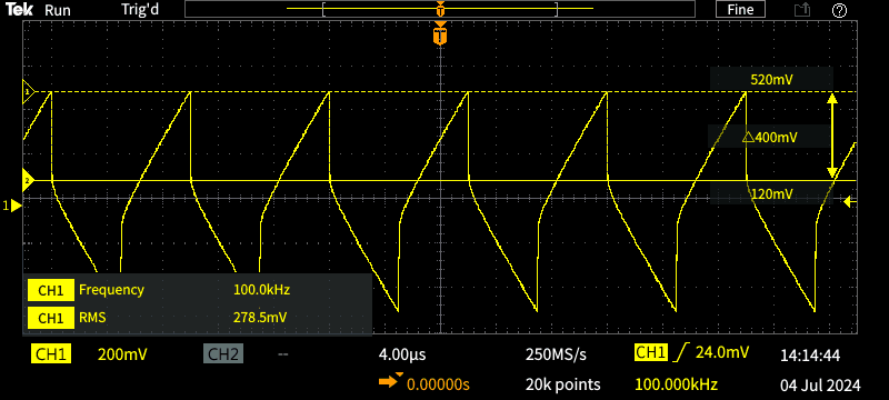
To get the trace shown, I used a 10V RMS squarewave with a feed resistance of 50Ω, so the current was ~200mA. I used a 2.2μF capacitor, and when the calculations are all done it works out that the ESR is 1Ω. As shown in Table 6.1, one ESR meter said 1.41Ω and the other 1.8Ω. These are inaccurate, but this really is a case of 'who cares?'.
It makes no difference if you use the positive or negative vertical transition, as they are (or should be) identical. This technique is probably more accurate than an ESR meter (especially with low-value caps), but accuracy isn't needed for the vast majority of tests that you'll perform. Note that the RMS voltage shown (278mV) doesn't look useful, because it's integrated by the capacitor under test. However, if you were to use that, you'd get a measurement (using Ohm's law) of 1.39Ω - that's actually closer to the real figure than an ESR meter can provide (see Table 6.1 which includes the same capacitor).

Note: It's highly unlikely that you'll get a usable reading from a multimeter, true RMS or otherwise. Even the scope will probably be inaccurate unless you use a properly compensated ×10 probe. I tested several meters I have (all true RMS), and at 100kHz their reading was unusable. At 1kHz they were all within ~3% (except one that was -7.5%), but a 100kHz they all clapped out (no significant reading) except one, which was 14% low and not at all useful. Needless to say the scope was accurate at any frequency I can generate.
As noted in the introduction, you can use a sinewave for testing, but usually not with a multimeter. If the capacitive reactance is more than ~25% of the ESR then that will become part of the measurement, and with a sinewave you can't separate the reactive and resistive parts. You should be able to get a fairly good indication of ESR with caps as low as 1μF, as low-value caps also have relatively high ESR. You can calculate capacitive reactance easily for a given frequency, with the formula ...
XC = 1 / ( 2π × f × C ) e.g.
XC = 1 / ( 2π × 100k × 1μ ) = 1.59Ω
Provided the expected ESR is at least 6Ω (for a 1μF cap for example, 4 times the reactance) the result of an ESR measurement can be quite accurate - within around 10%. This isn't wonderful, but it's quite satisfactory for an ESR measurement. Interestingly (and not intuitively), the reading will tend to be low with this technique. this is to be expected because the function generator impedance and the ESR form a voltage divider, where the voltage division is 17.7 with a 100Ω feed and a 6Ω ESR. The result using simple division (divide the input voltage by 16.7) is quite alright for the purpose.
These basically fall into the 'forget it' category for ESR. Most have extremely low ESR, and it's virtually impossible to measure it with test instruments available to mere mortals. I tried a number of different methods, and while it's (theoretically) possible, the tiniest bit of inductance creates resonance that makes a measurement almost impossible. I'd expect that if one could produce a 100V RMS squarewave that's fast enough, a measurement might be a success, but that's a lot of effort to go to produce a test system that you find still doesn't show anything useful.
I tested a 270nF film cap, and as near as I could measure, its ESR was close to zero. Getting an accurate measurement is almost impossible because the amplitude of the step was so small, and the scope's limits became a major error source. Even a tiny amount of inductance causes ringing, which makes accurate measurement (and even estimation) almost impossible.
Some capacitance meters will show the dissipation factor of the cap under test, and this is a good indication of the cap's losses (including ESR). Q is the reciprocal of dissipation factor, so a cap with a DF of (say) 0.015 has a Q of 66.7. Most C0G/ NP0 ceramic caps have a very high Q, as they are designed for use in RF tuned circuits, but electros (polarised or otherwise) are fairly poor. In theory, polypropylene caps have lower loss (and higher Q) than polyester¹/ PET/ Mylar types, but in most cases you'll be hard-pressed to pick a difference. For audio work it's a moot point, as capacitor Q is rarely (if ever) an issue, and the capacitor's dielectric does not affect the 'sound' (despite claims to the contrary you may find).
For RF caps and high loss components (e.g. electrolytics) the loss factor/ dissipation factor (aka tanδ [delta]) will usually be stated in the data sheets. You should be able to find the specified dissipation factor (DF), and/ or the tanδ. Of course, this assumes that you think this may have an effect - it won't for audio-frequency equipment, but can be critical for RF and high-speed switching (including SMPS).
tanδ = 1 / ( 2π × f × Rp × C ) Where Rp is the parallel resistance.
The effective parallel resistance (Rp) is extremely high for film caps, but can be quite low for electrolytic types (including tantalum). With ceramic caps it depends on the type of ceramic material used (Y5V, Z5U, X5R or X7R). Of these types, X7R are the most stable (or is that least unstable?). If the loss factor is too high, the cap will get hot with high current, and some caps will fail in some applications as a result.
¹ Polyethylene terephthalate (PET) is the most common form of 'polyester', and it's the same material used to make drink bottles. It's also known as Mylar®. It has a higher loss than polypropylene, but it's not significant unless the cap is passing high current at high frequencies. Polyester caps are not 'inferior' to polypropylene caps in most audio circuits (with the possible exception of passive speaker crossovers). Many still use bipolar electros when high values are needed, and they will degrade over time. Listeners don't seem to notice!
The first ESR meter I bought was the kit for the famous Bob Parker ESR meter. This was available from multiple suppliers, and it uses a microcontroller (Z86E0408 or Z86E0412 from Zilog) and it has a 2-digit LED display. I've had mine for well over 10 years (possibly closer to 20), and it is still a very good instrument. The other is my backup, and I'll sometimes use both to see how well they compare.
Most commercial ESR testers can resolve down to about 10 milliohms (0.01Ω), although some claim they have 1mΩ resolution. This may or may not be the case in reality, because low resistance values are hard to measure. The leads and connectors will have several milliohms resistance, although that can be reset to zero with the leads shorted. Ordinary alligator clips will have an uncertainty of a few milliohms, so expecting 1mΩ precision is unrealistic.
If you don't have a high-resolution ESR meter, then you have to accept relatively low accuracy. As already noted, this is of little consequence, as it's still very easy to see if a capacitor is within acceptable limits or not. If the chart says (for example) 6Ω for a 2.2μF 25V cap and you measure 3Ω, that's fine. If you were to measure 10Ω or more, the cap has passed its use-by date.
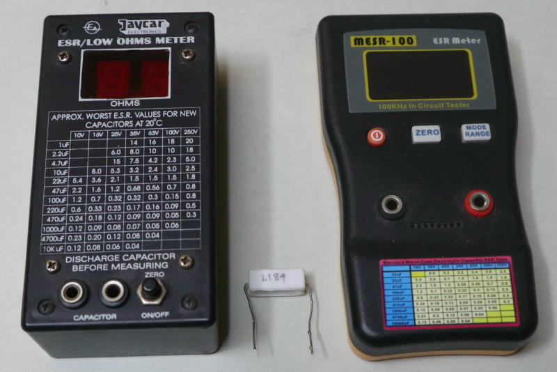
The test resistor was measured with a high-precision low resistance tester, and that showed 0.2184Ω (pencilled on the side as 2184). My multimeter can't get better than 10mΩ resolution, and it showed 0.21Ω. How did the two ESR meters perform?
The Jaycar/ Bob Parker meter gave a reading of 0.18Ω, and the MESR-100 showed 0.181Ω. This is perfectly alright for measuring ESR, but obviously it's unusable for getting an accurate reading with low value resistors or ESR. Both meters have a chart on the front showing roughly what to expect with various capacitor values and voltages, and these are a reasonable guide. If the chart says 0.32Ω but the cap under test measures 0.34Ω you have nothing to worry about. If it measures 3.2Ω, then it's clearly on the way out.
Some comparisons between the two meters are appropriate. Testing a resistor (to get a baseline) was the first step, and I used one that I'd measured accurately at 0.2184Ω. I also tested 3 electros, a 1μF 50V bipolar, 10μF 63V and 100μF 63V. Their value and dissipation were tested using my LCR meter, and the results are tabulated below.
| Cap / Meas. | MESR Meter | Jaycar Meter | Capacitance | Dissipation | Q |
| RRef | 0.213 | 0.21 | - | - | - |
| 1 μF Bipolar | 1.85 | 2.1 | 1.18 μF | 0.08 | 12.5 |
| 2.2 μF | 1.41 | 1.8 | 2.11 μF | 0.037 | 27.0 |
| 10 μF | 2.06 | 2.1 | 9.5 μF | 0.21 | 4.76 |
| 100 μF | 0.294 | 0.37 | 91.6 μF | 0.246 | 4.06 |
| 1 μF Film | 1.32 | 4.0 | 1.06 μF | 0.006 | 166.7 |
As you can see, the results are different between the two ESR testers. I don't know which one is right, but it doesn't really matter because both give measurements that are 'sensible', and the difference isn't really significant. I will happily use either meter, and I know that if a cap is 'bad' it will be immediately visible on either meter. The dissipation factor and Q show why electros are not usable in filter circuits - it doesn't matter how good the filter circuit is, it's performance will be ruined by the low Q of the caps.
This doesn't mean that they won't pass audio just fine, despite any reservations you may have. There's a school of thought (or is that 'thought' in deliberate quotes) that says that all caps are bad in the audio path, and electros will somehow ruin the sound. They do no such thing! Provided the signal level across an electro is low (meaning that the value is much higher than needed for the lowest frequency of interest), it can contribute little or no 'character' of its own.
I included a film cap just so you could see the difference. The reactance of a 1μF cap is 1.59Ω at 100kHz. This is out-of-phase with the resistive part, and is not a representation of internal losses. The very high Q shows us that the internal losses are negligible. Attempting to measure ESR will be an exercise in futility - I know this because I tried, and it was ... futile.
The upshot of all of this is that ESR needs to be measured (for electrolytic caps) if they are a few years old and where they are subjected to high stress. Some electros can easily last for 40 years or more in normal use, including those in valve amps where they are subjected to higher than desirable temperatures. The easiest way to test them is to use a dedicated ESR meter, but if you have a good function generator and a scope (everyone working with audio needs a scope!), you should be able to get a good idea using those. Like ESR meters, don't expect to be able to get a reliable measurement below 1μF (10μF is the lowest value where you can expect an accurate result from most ESR meters).
Fortunately, most circuits that use low-value electros don't subject them to significant ripple current, and failures are very rare. However, beware of high-voltage low-value caps! A typical 1μF 400V electro has a decidedly finite life - they are probably the least reliable electrolytic cap ever made. I've replaced many of them in LED lights, where they appear to be un-stressed, but are a consistent cause of failure. Most caps of similar ratings can also be expected to have a limited life.
As explained here, the ESR of film caps is almost impossible to measure. It's extremely low, and the inductance of the leads is enough to make a meaningful measurement impossible. ESL is not something that normally causes problems, but for high-speed circuits (along with RF) it's very important that capacitor leads and PCB tracks are as short as possible. Each centimetre of lead length adds about 10nH of unwanted inductance (it depends on the wire diameter, with thicker wire offering lower self-inductance). This is very real, but it rarely causes problems with audio-frequency circuits. ESR meters do not indicate ESL.
An ESR meter is invaluable if you're doing service work, but they are also useful for normal DIY activities. They aren't particularly cheap though - the MESR-100 will cost around AU$70.00 at the time of writing, and the Bob Parker unit is around €65.00 (AU$105.00) from Portugal. IMO this is money well spent unless you prefer to mess around with a function generator and a scope then calculate the ESR from the waveform. No? I didn't think so. 
Bob Parker ESR Meter
| Main Index Articles Index |