
|
| Elliott Sound Products | AN-018 |
 Main Index
 App. Notes Index
It's not all that often that you need a diode with ultra-low reverse leakage. A typical 1N4148 diode has a reverse leakage of between 1 and 1.5GΩ (at 25°C) with a reverse voltage of 10V, and this is sufficient for most common applications. Of course, you can buy diodes that are fully specified for low leakage. The BAS716 is rated for 5nA reverse current at 75V, which works out to 15GΩ. The BAS454A is better still, with 1nA reverse leakage at 125V (125GΩ). This increases to 500nA at a junction of 125°C (only 125MΩ) - it's highly temperature dependent (as with all diodes). You may find that some specialised types are rather expensive and/ or difficult to get from your local supplier. You will need to run your own tests, using the technique described in AN-016 to measure leakage resistance.
For these tests, I would normally use a test voltage of 10V, but I used a voltage of 25V because that made it a little more likely that I'd be able to measure something - however small. As it transpired, it made no difference if I'd used 10V or 25V (25V is at or below the collector-base or gate-source breakdown voltage for the BJTs and JFETs I tested). This was because the leakage was so low that I was unable to measure anything - even at the higher voltage. My bench meter has an input impedance of 11MΩ, so if I measure 1mV, the current through the meter is 9.09pA (Ohm's law).
Provided you have low current requirements, the collector-base junction of an ordinary bipolar transistor is very good indeed. I tested a number of BC546 transistors, and was unable to measure any reverse leakage (and my bench meter can (theoretically) resolve to 0.1mV). It didn't matter if the supply was connected or not, the meter steadfastly showed ±0.0002 (normal digit uncertainty for my multimeter). Even if I did manage get a reading of 10mV on my meter, that still represents a leakage resistance of 25GΩ! However, I was unable to measure anything ! When the transistor was heated I was able to measure some leakage current, but it was (literally) too hot to touch before leakage exceeded 1nA (25GΩ).
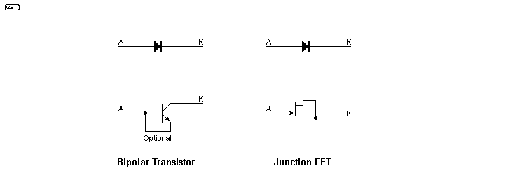
The drawing shows both a BJT (bipolar junction transistor) and a JFET (junction FET) used as diodes, with the diode symbols showing the polarity. The use of 'K' for cathode is standard nomenclature in case you were wondering, because 'C' is reserved for the collector of a transistor. However, the use of 'K' predates transistors, and has been used for as long as I can remember.

Figure 1 - NPN Transistor And N-Channel JFET As Low Leakage Diode
It's not uncommon to see JFETs specified for very low leakage diodes, but they usually aren't quite as good as a bipolar transistor. I tested a couple of 2N5459 JFETs (no longer available, but I had them in my parts drawer), and 'measured' a leakage current of about 45pA (~550GΩ). I say 'measured' in quotes because the value was so low, and I had to estimate the actual voltage displayed. However, this leakage increased very rapidly with heat, and it was no better than a 1N4148 even at a 'comfortable' temperature (I was unable to measure it, but I'd guess around 50°C).
Note that the maximum current is low (equal to the peak base current of the transistor or gate current for a JFET), so this technique is only suitable for currents that are typical in 'signal level' circuits. The emitter and base of a BJT can be joined or not - it made no difference in the tests I performed, but I wouldn't be happy having a terminal floating in a very high impedance circuit. In general, the current should be no more than about 10mA (continuous), but short-term pulses with higher current will (probably) do no harm. I would be very reluctant to use a transistor or JFET at more than 25mA peak. The requirement for ultra-low leakage is common in sample-and-hold circuits, especially if the hold period is more than a few milliseconds.
The other thing that must be considered is the junction capacitance, as that affects the switching speed. A BC546 has a typical value of 3.5pF, with a maximum of 6pF (10V between collector and base), while the two low-leakage diodes quote around 2-4pF, with recovery times of 0.3 to 3µs (which is pretty slow - a 1N4148 has a reverse recovery time of 4ns, almost an order of magnitude faster). This figure is not quoted for any transistor's collector-base junction, but can be assumed to be somewhat slower than a 1N4148, but faster than most low-leakage diodes.
Analog Devices show a diode-connected transistor in the OP77 datasheet, as part of a peak detector. They specified a 2N930, but there's no reason to expect that to be any better than the BC546 devices I tested. The collector cutoff current (collector to base voltage will be specified) is usually shown in datasheets as a 'worst case' value, and most will be far better than claimed. Leakage currents in the pA (pico-amps) range are common ... at room temperature. Leakage current increases exponentially as temperature is raised, so expecting good performance at elevated temperatures is unwise.
Note that if you use any of these techniques, the circuitry should be on Teflon (PTFE) standoffs or wired in 'mid-air'. Even PCB leakage can seriously degrade the total resistance, and this may make your circuit no better than a common 1N4148 diode if you aren't very careful with the layout.
Datasheets ...
Some info can also be found on the Net, but there are many conflicting opinions and not much real information.
 Main Index
 App. Notes Index