

|
| Elliott Sound Products | AN-013 |
 Main Index
 App. Notes Index
Most electronic circuits will be seriously annoyed if the supply is connected with the polarity reversed. This is often announced by the immediate loss of the 'magic smoke' that all electronic parts rely on. On a slightly more serious note, irreparable damage is often caused, especially with supply voltages of 5V or more. The traditional reverse polarity protection circuit consists of a diode, wired in series with the incoming supply, or in parallel with a fuse or other protective device that will blow.
A series diode reduces the voltage available to the circuit being powered. If it's running on batteries, the voltage reduction can easily mean that a significant part of the battery capacity is unavailable to the circuit. 0.7V isn't much, but it's a real challenge if the circuit relies on a voltage of at least 5V, and 4 x 1.5V cells only provides a nominal 6V. A series diode may also dissipate many watts in a circuit that draws high current - whether permanently or intermittently.
A parallel diode has to be robust enough to survive the full short-circuit current from the source until the fuse opens. That usually means a very large and expensive diode. A smaller one can be used, but in 'sacrificial' mode. That means it will likely fail (diode failure is always short circuit), but it must be robust enough to ensure that it doesn't become open circuit during the fault period due to bond or lead wired fusing.
A relay can also be used, and this has the advantage of virtually zero voltage drop across the contacts. However, relay coils draw significant current, and this can easily exceed the current drawn by the circuit being protected. If the supply is a large battery that has on-demand charging facilities this isn't a problem, other than the small cost of running the relay. In many cases though, this is not a viable option.
The alternative is to use a MOSFET. In many cases, it's a matter of the MOSFET alone, with no requirement for any other parts. This works if the supply voltage is lower than the maximum gate-source voltage, but additional parts are needed with voltages over 12V or so. The advantage of the MOSFET is that the voltage drop is vanishingly small if the right device is selected.
It's often possible to use a BJT (bipolar junction transistor) for reverse polarity protection as well, but they don't work as well as a MOSFET and have several inherent disadvantages that make them far less suitable. For a start, the base must be provided with current so the transistor will turn on, and this is wasted power. A BJT cannot turn on as hard as a MOSFET, so the voltage dropped across the transistor is greater. While it will usually beat a diode (even Schottky) there is no real advantage because the MOSFET is a far better option.
In the drawings that follow, there is a section simply marked as 'Electronics'. It shows an electrolytic capacitor and an opamp, but may be anything from a simple audio circuit, logic gates (etc.) or a microprocessor. Current drain may be anything from a few milliamps to many amps, and you need to choose the scheme that best suits you application. This is not a design guide, but rather a collection of ideas that can be expanded and adapted as required.
A series diode is the simplest and cheapest form of protection. In low voltage circuits, a Schottky diode means that the voltage drop is reduced from the typical 0.7V down to perhaps 200mV or so. This is very much current dependent though, and at maximum rated current the voltage drop may exceed 1V of a standard silicon diode, or around 500mV for Schottky types. Only the diode is required - no other parts are needed, so it is by far the simplest and cheapest.
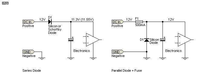
Figure 1 - Diode Protection, Series (Left), Parallel (Right)
While a series diode is dead easy to implement, as noted above there is a minimum 650mV or so voltage loss at low current, increasing with higher load current. With a 1A diode, the voltage loss will be close to 900mV at 1A, almost a volt reduction of the supply voltage. If the circuit is powered by batteries, this represents a serious loss of capacity, because around 900mW of available power is wasted for no good reason. If you have plenty of power to spare, or with high voltages (25V or more) the diode loss is insignificant.
A Schottky diode is better, but they are usually more expensive, and are not available for high voltages. For a 1A Schottky diode, you can expect to lose around 400mV at 1A. Schottky diodes have a forward voltage ranging from 150mV to 450mV, depending on manufacturing process, current handling rating and actual current. Maximum reverse voltage is around 50V, but reverse leakage is higher than standard silicon diodes. This may cause problems with sensitive devices, but usually not. The (more or less) typical voltage with a Schottky diode is shown in brackets. A series diode can be 'assisted' by a parallel diode on the equipment side if diode leakage is likely to cause problems. This is rarely needed or used in practice.
With a parallel diode (sometimes referred to as 'crowbar' protection), it must be rated for a higher current than the source can provide. If the voltage source is batteries (any chemistry), they can deliver extremely high current, so some means is needed to disconnect the circuit - preferably before the diode overheats and fails. Although diodes fail short-circuit in 99% of cases, this is not something that you'd want to rely on to protect expensive electronics. Some power supplies may object to a shorted output, and may current limit or fail.
A fuse is the easiest and cheapest way to disconnect the supply if it's connected in reverse, and the fuse must be rated to carry the maximum current expected by the circuitry. There is no voltage lost across the diode in this arrangement, but there is a small voltage lost across the fuse. This voltage drop is usually insignificant. Naturally, if the supply is connected in reverse, the fuse will (should) blow, and the diode may or may not survive. This means that the system must be checked and repaired if necessary should the supply be reversed at any time, including fuse and/or diode replacement. You may be able to use a 'PolySwitch' PTC (positive temperature coefficient) thermistor switch - this depends on many factors that need to be researched first.
While it may sound like a silly idea at first, a relay is an excellent way to provide reverse polarity protection. This is provided the voltage source can power the relay without reducing its capacity. In battery powered equipment, this is usually not an option, but it can be useful for equipment in cars or trucks, where the battery has high capacity and is continuously charged while the engine is running. A relay should not be used for any equipment that is connected permanently, as it will discharge the battery eventually.
As you can see below, the relay coil can only get current when the polarity is correct. With positive at the (positive) input, D1 is forward biased, and the coil receives about 11.3V which is more than sufficient for it to pull in. When the N.O. (normally open) contacts close, power is applied to the electronics. If the polarity is reversed, no current flows in the coil and the electronics are completely isolated from the supply because the relay cannot activate.
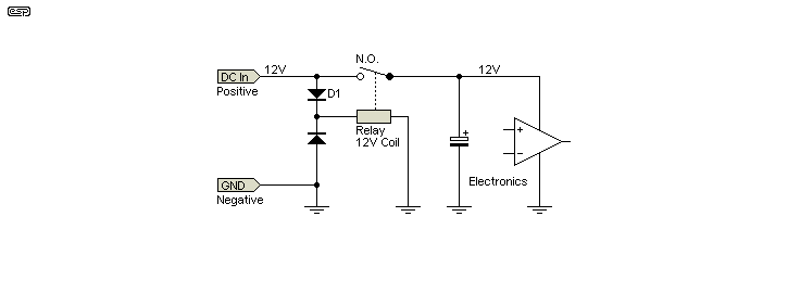
Figure 2 - Relay Protection
The advantage of a relay is that it can handle extremely high current with almost no voltage drop across the contacts. Relays are rugged, and can last for many, many years without any attention whatsoever. They don't need a heatsink (regardless of current drawn), and are readily available in countless configurations and for almost any known requirement. Automotive relays will also have already passed all the mandatory tests required, so can reduce the cost of compliance testing where this is a requirement.
The inherent ruggedness of a relay is a huge advantage in automotive applications, where 'load-dump' events are common. These occur when a heavy load is disconnected from the electrical system, and the alternator is unable to correct quickly enough to prevent over-voltage. There are other causes, and all automotive equipment must be designed to withstand significant over-voltage without failure. Relays can manage this with ease.
Relays are available with many different coil voltages (e.g. 5, 12, 24, 36, 48V), and there are models for any conceivable contact current requirement. Where the input voltage is too high for the coil, a resistor can be used to reduce the voltage to a safe value. An 'efficiency' circuit can also be incorporated (a series resistor with a parallel electrolytic capacitor) that pulses the relay with a higher than normal voltage to pull it in, then reduces the current as the cap charges to a value a little more than the guaranteed holding current (determined by the resistor). The holding current can be as low as 1/3 of the nominal coil current, sometimes less.
MOSFETs have a very desirable feature. They all have a reverse diode which determines the voltage polarity, but when a MOSFET is turned on it conducts equally in either direction. So, when the diode is forward biased and the MOSFET is on, the voltage across the MOSFET is determined by RDSon (drain-source 'on' resistance) and current, and not by the forward voltage of the diode. This useful property has made MOSFETs the device of choice for reverse polarity protection circuits.
However, you must consider the fact that MOSFETs require some voltage between gate and source to conduct, and in a very low voltage circuit (less than 5V) you may not have enough voltage available to turn on the MOSFET. Logic-level MOSFETs can turn on with lower voltages than standard types, but are also more limited in terms of RDSon, and fewer devices are readily available - especially P-Channel types.
In the drawing, a resistor and zener diode are shown. These provide gate protection for the MOSFET's gate if there is any chance that the maximum gate-source voltage may be exceeded. While they can be omitted, it's generally unwise to do so. Should a transient spike exceed the gate's breakdown voltage (typically around ±20V), the MOSFET will be damaged, and will almost certainly conduct in both directions. This negates the protection circuit completely!
For equipment that is powered from batteries it is unlikely that a 'destructive event' will occur, but the MOSFET's gate may still be damaged under some circumstances. It appears unlikely, but a high reverse voltage (static for example) may cause breakdown if protection isn't used. Some MOSFETs have an in-built gate zener, and the resistor is then essential to prevent destructive current with voltages greater than the zener voltage.
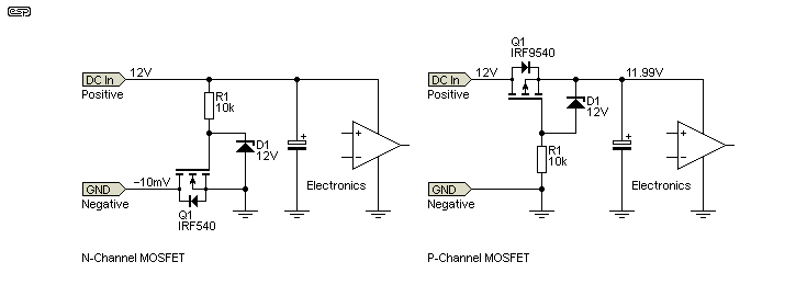
Figure 3 - MOSFET Protection - N-Channel (Left), P-Channel (Right)
You can use N-Channel or P-Channel devices, depending on the circuit polarity and whether or not you can interrupt the earth/ ground connection without causing circuit misbehaviour. In an automotive environment, the chassis is the negative supply, and it's difficult or impossible to interrupt it. That means that the protection circuit must be in the positive supply rail, which is slightly less convenient because it usually requires a P-Channel MOSFET. These are usually lower power and current than their N-Channel counterparts. You can still use an N-Channel device, but it's more irksome and needs more circuitry (shown below).
If you use a P-Channel MOSFET, there is no interruption to the earth/ ground (negative) connection. This is useful with automotive electronics in particular. However, there are some limitations that you must be aware of. The most important (and the one most likely to cause problems) is the required gate-source voltage. This isn't an issue with automotive applications because 12V is available, but it's a concern for lower voltages.
Logic level (5V) P-Channel MOSFETs are certainly available, but as noted they are very limited compared to N-Channel types. They are also usually more expensive for equivalent current ratings, and many are only available in surface mount (SMD) packages. This does limit their usefulness in low voltage, high current circuits, where it's not possible or sensible to interrupt the negative rail (allowing the use of N-Channel devices).
Where the voltage is otherwise too low to turn on a MOSFET, there is the option of using a charge-pump circuit to bias on an N-Channel device. This adds complexity and cost, but is a viable option when other methods are unsuitable for any reason. The charge-pump is used to generate a voltage that's greater than the incoming supply (typically by around 10-12V or so), and this voltage turns on the MOSFET. The general idea is shown below, but the details of the charge-pump are not provided - it is a 'conceptual' circuit, rather than a complete solution. Protective diodes shown may or may not be necessary, depending on the circuit.
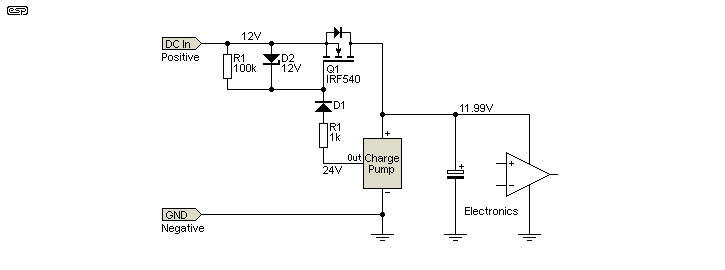
Figure 4 - N-Channel MOSFET With Charge Pump
There are many different ways the charge pump can be designed, and the circuit is outside the scope of this article. However, it must be arranged so that the charge pump itself cannot be subjected to reverse polarity. When power of the correct polarity is applied, the intrinsic diode in Q1 conducts and provides power to the charge pump and the rest of the circuit. Within a few milliseconds, the charge pump has produced enough voltage to turn on Q1, and the MOSFET turns on and bypasses its own diode. The voltage loss is determined purely by the on resistance of the MOSFET and the current drawn by the circuitry. An encapsulated DC-DC converter (with a floating output) can replace the charge pump if preferred.
Use of a BJT is appropriate for low current loads, but where the voltage may be too low for a MOSFET because there's insufficient gate voltage for it to turn on properly. In the examples shown below, there is about 125-150mV drop across the transistor with a load current of 40mA. The voltage drop is far less at lower currents. R1 must be selected to ensure that there is adequate base current to saturate the transistor. This usually means that you need to provide at least three and up to five times as much base current as you would calculate from the transistor's beta.
For example, a transistor with a gain (Beta or hFE) of 100 needs 400µA for 40mA load current, but you should supply no less than 5mA or the voltage dropped across the transistor will be excessive. In the drawing, the transistor is assumed to have a gain of at least 65 (from the datasheet), and the 2.2k resistor provides about 2mA base current - this keeps the loss below 50mV at 40mA. It is unrealistic to expect much better than this without the base current becoming excessive. The transistor will dissipate less than 10mW with the circuits shown. You can use a small signal transistor (e.g. BC549 or BC559) for low current loads.
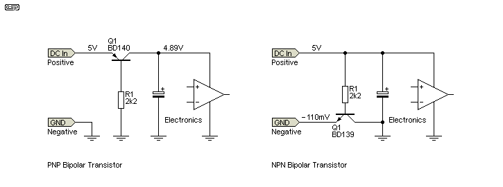
Figure 5 - PNP Transistor (Left), NPN (Right)
There is an inherent limitation with using a BJT, and that's the emitter-base reverse breakdown voltage. With most, the breakdown voltage is rated for around 5V, although it might be greater for some examples. That means that having an input voltage greater than 5V is probably unwise, because the emitter-base junction will be reverse biased. This causes degradation of the transistor's performance and may pass some reverse voltage to the electronics. A complete breakdown may pass the full reverse voltage to the electronics, resulting in failure. This issue appears to have escaped detection in most of the circuits I've seen.
An NPN transistor is supposedly better, because they usually have higher gain and therefore lower losses due to a higher resistance being used to supply the base. In practice the difference will be marginal at best. Like an N-Channel MOSFET, NPN transistors must be used in the negative lead and require that the negative input and chassis can be isolated. The same problem of reverse breakdown of the emitter-base junction applies.
As always in electronics, each of these circuits offers advantages and disadvantages. You need to choose the option that is most suitable for your application, based on the current required, available voltage and permissible voltage drop. In commercial products, cost may be an over-riding factor, often at the expense of better performance.
In some cases, the product may require survival when subjected to high pulse energy as part of the test and/or approvals process. This can be difficult to achieve with some of the mandated high-energy pulse tests used by various agencies worldwide, and it's also something that must always be considered in automotive applications, where 'load-dump' spikes can cause high voltage spikes throughout the vehicle's electrical system. Consequently, the info here will be no more then a starting point for some applications. Thorough testing is needed for any product intended for a hostile environment.
You also have to consider the likelihood (or otherwise) of reverse voltage being applied. In many cases, it's something that can only ever happen when the product is assembled, and if that's done in such a way as to all but eliminate errors, reverse polarity will never come about. Most products don't have internal polarity protection if they are powered from the mains. This is because once the equipment is assembled, there is no possibility that the polarity can ever be reversed, other than someone inexperienced trying to service it. Few (if any) products make allowances for errors made during servicing.
If your circuit can handle the voltage drop from a diode and draws low current, a simple blocking diode (standard or Schottky) is probably all that's needed. Don't assume that because the MOSFET circuit has the best performance it is automatically the best choice. That performance comes with increased cost and has its own special limitations. Good engineering should minimise cost and complexity, and provide the approach that best meets your design requirements.
Finally, never underestimate the use of a relay. They are one of the oldest 'electronic' components known (actually they're electro-mechanical, but that's beside the point.  ) Their ruggedness and versatility is unmatched by any other component, and the fact that they are still used in their hundreds of millions is testament to that fact. The down side is their coil current, but that is often of secondary importance.
 Main Index
 App. Notes Index