
|
| Elliott Sound Products | AN-004 |
 Main Index
 App. Notes Index
There are countless dome light extenders on the Net and in magazines, but most of them suffer from one problem ... complexity. Ok, they are not actually complex, but most are far more complex than they need to be. Some are completely over the top, and require additional car wiring, a PCB, ICs, trimpots and lots of other stuff, while others seem to be someone's untested idea or maybe just a brain fart - some circuits I saw will never work. My goal was extreme simplicity, and I think that has been achieved. It is helpful if it works too - there's not much point making it otherwise. Efficiency is not an issue, since the dimming phase is relatively short lived anyway. Worst case dissipation in Q2 should not exceed about 2W or so (momentary) with a standard 6W dome lamp.
As with so many projects on the ESP site, this came of necessity (or is that desire?). My car has most of the bells and whistles that one expects these days, but the dome light switched off as soon as the door was closed. I figured that about 15 seconds was a reasonable time delay, and I only had a very small space in which to locate the unit - namely in the dome light housing itself.
Not much to it, really. It is obviously important that the existing car wiring be used - the last thing one wants to do is have to run additional wires in a car. Standard dome lights use the door switch to make the negative connection to the lamp, with the positive being permanently connected to the car's positive battery terminal (via the obligatory fuse).

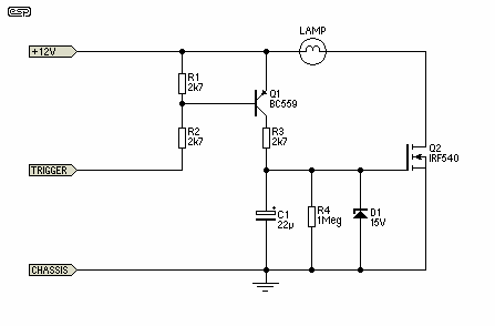
Figure 1 - Dome Light Extender Schematic
As you can see, it is very simple. Cheap (mainly 'junk box') transistors are used throughout, and the resistors can be very ordinary carbon film types. The cap only needs to have a voltage rating of 16V, but higher voltage caps can be used if you have them to hand.
When the car door is opened, the 'Trigger' terminal is connected to chassis. This turns on Q1, which promptly charges C1, thus turning on MOSFET Q2. Provided there is enough gate voltage for Q2, the lamp will remain on, but as the cap discharges the gate voltage gets to the point where Q2 is no longer saturated and the lamp starts to dim. As the cap discharges further, the lamp dims more, eventually going out altogether. Full brightness remained in my circuit for about 20 seconds, and the lamp was extinguished within 22 seconds.
Because a switching MOSFET has a fairly rapid transition from conducting to non-conducting states with a relatively small voltage range between fully on and fully off, that makes the ideal switch. The transition period is quite narrow, so no heatsink is needed. Timing is also reasonably predictable, since it is determined by the resistor and cap. A low value cap can be used, minimising size. The zener is essential to protect the gate against transients (all too common in a car's electrics). The resistor (R3) provides a high impedance for any transients so they don't just blow the zener and the MOSFET gate.

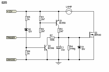
Figure 2 - Dome Light Extender With Voltage Detector
Figure 2 shows an enhanced version, that uses Q3 as a battery voltage detector. When the engine is off, Q3 remains off too, because the zener (D2) doesn't have enough voltage to conduct. C1 therefore discharges through R4 normally, and the full timeout period applies. When the engine is running, the battery voltage quickly rises to ~13.8V (the normal float charge voltage for a lead-acid car battery. This allows D2 to conduct, turning on Q3, and discharging C1 via R7, so the cap is discharged much faster.
This addition was made to my unit after I fitted a (home made) LED light to replace the silly incandescent bulb. Because the new LED lamp is so bright (yet only draws about 200mA), it became annoying at night because it was too bright inside the car. By adding the extra bits, it now extinguishes in about 4 seconds when the engine is started or is running. There is now plenty of time to get organised having opened the door and clambered in, but when the engine is started the lamp goes out much more quickly. R7 can be reduced in value if faster operation is required. It can be reduced to about 22k to get a really fast turn off. If the value is too low, the lamp will not turn on at all if the engine is running.
Nothing is critical, except that all the usual precautions against short circuits must be taken. If the time delay is too long (or short), simply reduce (or increase) the value of C1 or R4 as appropriate. Because of the design, the existing wiring in the dome light is retained except that the door switch lead needs to connect to the trigger input, rather than directly to the lamp. R7 can be reduced as well to get a faster turn-off when the engine is running.
The resistor values shown are a guide only, and the circuit will work fine with a fairly wide range of values. Those shown are not bad though, so feel free to use them. Likewise, almost any small signal PNP transistor can be used, the MOSFET can be almost any N-Channel switching device capable of at least a couple of amps.
Since the typical dome light is only rated at about 6W (0.5A at 12V), high current wiring is not necessary. Just make sure that everything is properly insulated so that nothing can short to chassis.
I suggest that the dome light switch is wired directly to the lamp as normal - if possible (not all switches will allow this). This prevents the delay from operating should you turn on the interior light, so it goes off immediately when switched. While it is possible to add an extra transistor to reduce the on time if the engine is running (as suggested in at least one circuit I saw), this would normally require running an extra wire - an exercise in futility with most cars.
The method shown in Figure 2 does not require any additional wiring, and is probably the easiest way to modify the timing to make the lamp turn off faster when the engine is running.
 Main Index
 App. Notes Index