
|
|
| Elliott Sound Products | Phase, Time and Distortion in Loudspeakers |
 Main Index
Articles Index
Main Index
Articles Index
One only needs to look at a few web sites to realise that there is actually very little useful information on phase in audio systems in general, and loudspeakers in particular. There are a great many conflicting claims and counter claims, but little real data. There is naturally a great deal of rubbish, mostly describing why 'Brand X' loudspeaker (for example) is demonstrably superior to every other speaker on the planet (which is why no-one has ever heard of them). Expect to see claims that "this speaker is the only design that will accurately reproduce a square wave" or something similar. As we shall see, this is realistically possible, but has (or should have) a huge "who cares" factor that will be discussed in greater detail a little later.
This article is not for the faint hearted, as it discusses amplitude, phase and delay, and the complex interactions between them. There is only so much that can be accomplished by diagrams and graphs, and many of the concepts do not lend themselves to easy analysis. I have tried to keep the information in a logical form, but unfortunately, all of the things discussed occur simultaneously. This is not always easy to visualise, and is even harder to write.
The many diagrams and graphs were produced using SIMetrix, an excellent simulator available from SIMetrix in the UK (SIMetrix). It is available as a free demo system, and is the best simulator I have used so far.
Since I am going to be using a 6 dB/ octave filter for many of the examples below, Figure 1 shows the response of a conventional 1st order (6 dB/ octave) filter. This is normalised to 10k ohm and 10nF. These values used for most of the response examples in this article, and give a crossover frequency of 1.59kHz. Although many discussions will revolve around different frequencies, this is of no consequence. The graph is designed to show the rolloff slopes of the high and low pass sections - not the absolute performance at any specific frequency.
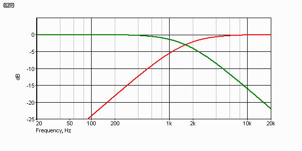
Figure 1 - 1st Order High and Low Pass Response
The red trace is the high pass response, and the green is low pass. The summed output is not shown, but has a perfectly flat frequency response. The simulator actually claims slightly different -3 dB frequencies for the two signals - this is not a simulator aberration, but the result of the simulator calculating to the absolute limits of accuracy. The crossover frequency is in fact 1.59kHz as calculated, and at that frequency, the level is exactly 0.707 volt. If expressed accurately, -3 dB is in fact 0.7079, and not 0.707 as is commonly used. This is a small error, and may safely be ignored.
All filters come with some pretty rigid rules - these are determined by the laws of physics, and are not open to discussion, although some of the snake oil vendors will still try. Filters are described in 'orders' - 1st, 2nd etc. Each order has an ultimate rolloff (i.e. achieved at some point distant from the cutoff frequency) that increases by 6 dB steps for each successive order, so 6, 12, 18, 24 dB/ octave is a common way to describe the filter's response. They are further divided into 'even' and 'odd' order (even and odd numbers - it doesn't matter much, but is commonly used anyway).
A brief numerical description of each filter type is shown below, along with its rolloff characteristics and power level above the cutoff frequency, typically defined as that frequency where the response is reduced by 3 dB. This is not always used as the crossover frequency - Linkwitz-Riley aligned crossovers use the -6dB point instead, and achieve a flat response as a result (not applicable to 1st or 3rd order filters).
| Order | Slope | Voltage | Power | Theoretical |
| None | Flat | 1 Volt | 1 Watt | 1 Watt |
| 1st | 6 dB/ octave | 439 mV | 193 mW | 250 mW |
| 2nd | 12 dB/ octave | 371 mV | 138 mW | 64 mW |
| 3rd | 18 dB/ octave | 195 mV | 38 mW | 16 mW |
| 4th | 24 dB/ octave | 122 mV | 15 mW | 4 mW |
Voltage in the above table is the voltage one octave above the -3dB frequency (assuming an input of 1 Volt and a low pass filter), and power at the same frequency, referred to 1 Watt. For example, 138 mW is about 1/7th Watt. The performance of a high pass filter is exactly the same as shown. The 'theoretical' value quoted is the power that should appear in theory, based on the assumption that the filter's rolloff slope is a straight line. It's not straight by any means until the frequency is at least a couple of octaves beyond the -3dB frequency. You may even see the 'theoretical' value quoted by manufacturers who have neglected to actually perform the maths, and have simply used the filter rolloff to arrive at a convenient/ impressive looking number.
The above is not exhaustive, but it covers the filters most commonly used in audio. For all filters above 1st, the table is based on a sub-Bessel (minimum settling time) alignment having a Q of 0.5, which is also typical of Linkwitz-Riley designs. This excludes 3rd order filters, which are (nearly) always Butterworth, and sum flat because there's a 90° phase shift between the two outputs (the same applies to 1st order filters).
There is now (after a mere 19 year delay) a new article that covers the design of group delay filters in some detail. These are the alternative to stepped baffles and other 'mechanical' means of achieving time-alignment. While there is a bit of info here on the use of phase-shift networks to create a time delay, it's far from complete. I chose to produce a new article rather than add the details to this on, for the simple reason that this is already a long article, and I didn't want to make it longer.

| Note: For all the following graphs, the speaker displacement is assumed to cause a 145µs delay, and the crossover frequency is 1.59kHz (10k and 10nF for first & second order filters). Different displacements and crossover frequencies will give different results, and this must be considered when making calculations. |
Firstly, there are many ways that the phase of a wave can be shifted, with the most common being time delay. At its most extreme, there is a delay of days to decades between the material being recorded and you listening to it - and no, this is not meant as a marginally humorous comment - this is a genuine time delay. The important thing is that all of the signal is delayed by the same amount, and it doesn't matter if this delay is measured in milliseconds or millennia, the sound will emerge intact and completely recognisable.
The situation is very different if some of the sound is delayed, while the rest is not (this is commonly referred to as group delay, and is discussed later in this article). The listening experience would not be enhanced if the high frequencies were to be reproduced half an hour later than the bass or vice versa. This is quite obvious, but let's reduce the time to something more realistic. What if the treble were to be delayed by 20 milliseconds? The effect would be awful - this is a time difference we can easily pick, as we use these cues to determine the original sound from reflected sound for localisation.
We can continue reducing the time delay, and the effect will become less and less discernible as the time is reduced. Finally, we get to a point where the delay represents less than a wavelength (in air), and (perhaps surprisingly), the differences are still audible. Consider a 1kHz sine wave, reproduced from two sources, but with one delayed by 500µs - just 1/2 millisecond. As one source creates a compression, the other creates a rarefaction - the waves are 180° apart, and will attempt to cancel each other. Early reflections, diffraction, and a multitude of other effects will ensure that we still hear the sound (at least at that frequency), but there will be a very noticeable drop in level.
Now, there are some who will claim that reversing the phase of one source will bring everything back to where it was, so there is no harm done, and the net result is the same as if the two sources were not delayed at all. While this will obviously work at 1kHz, at other frequencies this is not the case.
Now, let's look at some of the physics involved here. How would a 500µs delay be introduced in the first place? In reality, this is not uncommon, but we shall reduce the time delay to something more realistic before continuing. Any two loudspeakers that reproduce the same signal at the same time will exhibit this phenomenon, but for our purposes on a smaller scale.
If we look at a midrange driver and a tweeter, in the common vertical alignment in an enclosure, we have a time delay. The 'acoustic centre' of the tweeter will most likely be a small distance closer to the listener than that of the midrange driver, and for the sake of this discussion, let us assume a difference of 50mm, because it is a realistic offset for common loudspeakers. Some will have more offset, others less.
Before continuing, it is important that the concept of 'wavelength' is properly understood. Sound travels at about 343 m/s at 20°C in dry air at sea level. This changes with temperature, humidity and altitude, but we shall not concern ourselves with this, and there is little we can do about it most of the time. A sound at 343Hz has a wavelength of 1 metre, at 34.5Hz the wavelength is 10 metres, and at 3,450Hz, it is 100mm. This is quite linear, and works for all frequencies. Another useful thing to know is the period (the actual time required to reproduce one cycle at the selected frequency). The symbol for wavelength is lambda ( λ ).
wavelength ( λ ) = velocity / frequency
period = 1 / frequency
From the above, we can calculate the wavelength for any frequency we like. 3,000Hz has a wavelength of 115mm, for example.
If we return to the midrange and tweeter mentioned above, their acoustic centres are offset by 50mm - this is exactly 1/2 wavelength if the crossover frequency is 3,450Hz. We can account for the 1/2 wavelength by reversing the wires to the tweeter, so it is 180° out of phase with the midrange. The two drivers are now aligned in phase, so in theory, they are time aligned. Unfortunately, this is not the case. Although the signal is in alignment at the crossover frequency, it will not be aligned any more when the frequency changes.
What is really needed is to delay the signal going to the tweeter by 145µs (1/2 of the period of a 3,450Hz waveform), or align the acoustic centres of the two drivers in the vertical plane. Such 'time alignment' is commonly achieved by angling the baffle so that at the listening position, the signals are properly in phase and time. Stepped baffles have also been used, but often create more problems with diffraction than are solved by the time alignment.
In short, time alignment is a good goal, but does not necessarily guarantee that the sound will be any better than a conventional flat baffle, with the phase of the drivers appropriately switched to ensure that the signal is in phase at the crossover frequency. It must be understood that with any flat baffle, an octave each side of the crossover frequency will see the phase out of alignment again, so it is essential that a high order crossover is used to prevent unwanted cancellations and reinforcements at different frequencies. A point often missed in loudspeaker design is that the acoustic centre is not some fixed location (such as the centre of the voicecoil), but varies with frequency. This variation is not always predictable either, making things harder for the designer.
With a flat baffle and a time displacement, above or below the crossover frequency the signals are in and out of phase - the exact amount can be calculated, and this can be very important in the greater scheme of things.
| Octave | Frequency | Wavelength | Phase Angle |
| -1 | 1,715 Hz | 200 mm | 90° |
| -1/2 | 2,425 Hz | 141 mm | 45° |
| 0 | 3,430 Hz | 100 mm | 0° |
| +1/2 | 4,851 Hz | 70 mm | 90° |
| +1 | 6,860 Hz | 50 mm | 180° |
Expect a dip at an octave above the crossover frequency, since the two signals (from the midrange and tweeter) are 180° out of phase at this frequency - not because of the crossover, but because of the time delay of 145µs. The only way to ensure that this dip is inaudible is to use a steep filter! If a 6 dB/octave filter were to be used, the signal level is only down to 0.447 of the total (7 dB). On the other side, at 1 octave above crossover frequency, the tweeter will only have 0.894 of the full signal (0.97 dB down). These voltage relationships can be seen in Figure 1, above.
Hang on - this is a 6 dB/ octave filter, and it's 7 dB down an octave from crossover frequency. How can that be?
Remember that we are already 3 dB down at the crossover frequency, but because a 1st order crossover has a very low Q (or in other words is highly damped), the rolloff is not as steep initially as expected. It should be down by 9 dB an octave away, but this will never happen.

Figure 2 - Amplitude and Phase Response of 1st Order Filter
Ignoring the acoustic centres of midrange and tweeter for a moment, Figure 2 shows the waveform response of the filter at crossover frequency, together with the input signal. The RMS voltages of each are quite predictable - the two filtered signals are 0.707 of the input voltage. The waveforms above or below crossover frequency are not shown - the absolute phase will be different, but relative phase (between outputs) remains at 90° for all frequencies. This is the electrical response only - the acoustical response will be different if the drivers are not time aligned!
Now (and this is where it gets tricky), what happens if we sum the electrical signals reproduced by the simple 1st order crossover? Assume an input of 1 volt for convenience. Adding 894 mV and 447 mV algebraically (at any frequency) will give an output of 1.34 volts - this is clearly not correct, since the input is only 1 volt to begin with.
As noted, analysis of a 6 dB/ octave crossover shows that the high and low pass signals are in fact 90° out of phase at all frequencies ...
Yes but ... isn't the 1st order crossover supposed to be phase coherent? I've looked at heaps of web sites that say the 6dB crossover has perfect phase response!
Yes and no. It is phase coherent in that all signals at all frequencies are 90° out of phase. I know that you have seen web sites that say that there is no phase shift through a 1st order crossover, but this is simply untrue! At crossover, the high pass section is leading - the signal appears to emerge from the filter 45° before the input. This would not seem possible, but is normal behaviour with all filters when a 'steady state' signal is applied - you don't have to really understand it, so I suggest that you just live with it.
The low pass filter has a lagging response, so the signal emerges 45° after the input. This is easier to comprehend, but may still seem a little strange (which I suppose it is for a filter that many claim has no delays).
So, if we make the essential correction, and shift the relative phase of either signal by 90°, we can recalculate the summing of the two signals. Predictably, 894 mV + 447 mV with a 90° phase shift now gives a summed response of 1V - this is as we would expect.

Figure 3 - Summing the Outputs of a 1st Order Filter
You can see the phase relationship between the 3 signals quite clearly. The red trace is the sum, green is the high pass output and blue is the low pass. The applied frequency is about 1 octave below the crossover frequency. I doubt that this will be terribly meaningful for the most part, but it is essential to the understanding of the relationships - time and phase are inextricably entwined with each other, and cannot be separated.
The electrical and acoustical relationships only coincide if the acoustic centres of the speakers are in exact alignment. As soon as there is a misalignment (introducing a time delay), everything changes. To see the effect, imagine the original setup, with the acoustic centres misaligned by 50mm. The tweeter's output will now be heard 145µs before that of the midrange. For the purpose of explanation, we shall ignore the 90° phase shift introduced by the crossover, and indeed, this is only present in the 1st order design. In fact, for many of the following explanations I will use signals of equal amplitude, and will ignore the crossover altogether. This provides for a worst case - reality will be somewhat tamer.
If we use two signals of equal amplitude, when summed we get a signal of double that of each signal - after all, the concept of 1 + 1 = 2 is not uncommon (except in government and some corporate financial circles  ) If the level is any different, then there is phase shift (or delay) that causes the error.
Figure 4 shows what happens when the 3,450Hz signal is produced from both speakers simultaneously, but with a 145µs time delay (representing the 50mm offset). The red line is the combined signal - there is no signal! This is electrical summing, which is much more critical than acoustical summing, so in reality we will still hear something, but nowhere near what we should. This is commonly referred to as a 'suckout' by reviewers, and there will be a pronounced dip in frequency response. Now, we know that this is easily fixed by reversing the phase of one driver, and everything will be back where it should be - but (and this is the clincher here) - only at one frequency! At all other frequencies there will be interference effects, and the lower the filter order, the worse it becomes.

Figure 4 - Two 1V, 3,450Hz Signals, With One Delayed by 145µs
Rather than take vast amounts of bandwidth to display as whole series of similar waveforms, I have tabulated the resultant signal level below, for 2 signals of equal amplitude but with one delayed by 145µs. These are the same frequencies we looked at earlier. In all cases, the result should be 2 volts ...
| Octave | Frequency | Amplitude |
| -1 | 1,715 Hz | 1.414 V |
| -1/2 | 2,425 Hz | 0.887 V |
| 0 | 3,430 Hz | 0 V |
| +1/2 | 4,851 Hz | 1.195 V |
| +1 | 6,860 Hz | 1.959 V |
Now, bear in mind that the above table is actually meaningless (it looks impressive though). All of the information must be presented in a simultaneous manner for any of it to make real sense. To expand on this a little further, have a look at a frequency scan of two drivers reproducing the same signal, but with one delayed by 145µs. This produces a comb filter effect. Now, in real life, the signals will not be at the same amplitude, so the effect is reduced. The signals are also summed acoustically, reducing the effect even further, but the crucial point here is that the crossover and acoustical summing reduce - not eliminate - the problem. But this is still not real! (It is marginally useful though, just so you can see where all this is going.)

Figure 5 - Comb Filter Created by 145µs Delay
We can see the notch predicted in earlier examples at the crossover frequency of 3,450Hz, but we also see another at 10.26kHz, and another at 17.4kHz. The final notch shown is unlikely to be audible for most of us at 24kHz. If the delay is increased, the effect becomes worse. It is also worth noting that even with the relatively small delay used for this example, the combined signal is down 3 dB at 1,737Hz. Remember that this is worst case, with no crossover network.
The combined effect of the delay and crossover can be expected to be a little less daunting, so the trusty simulator has been stretched a little here, and Figure 6 shows what happens when both the delay and the crossover are used, with the phase of one driver reversed as required to prevent the cancellation at crossover frequency. Oh dear! There might not be a major problem at the crossover frequency, but the peak and dips affect all frequencies from below 1kHz to well past 20kHz. Less daunting? When all the material is presented, then the whole picture is available.
Note that this was missed in the table above, since I only looked at the 1/2 octave boundaries and with equal amplitudes. Little omissions can leave major gaps in ones actual knowledge! A small (cunningly disguised) trick of calculation or description can leave one thinking that a designer has achieved something special, so always make sure you have all of the information.

Figure 6 - Combined Crossover and Time Delay Response (6dB/ Octave)
The effect is not as severe (note the peaks and dips - read the dB levels!), but in quite a few respects it is almost as bad as the 'fake' graph of the previous example!
Just to make sure, I reduced the time delay to 10µs then 1µs, to verify that nothing was awry with my simulations. As expected, the response was almost flat, and with no delay at all, the response was completely flat.

Figure 7 - Response With 12 dB/ Octave Filters
So, the next question has to be ... What difference does it make if the filter order is increased? Figure 7 shows the response with a 2nd order filter, using a Linkwitz Riley alignment. The ripples (in particular the dip) have been increased - hardly a desirable outcome. If one of the drivers is not reversed (wired out of phase), the frequency where the dip appears is changed from 1.16kHz (as shown) to 2.67kHz.
Figure 8 shows the response with a 24 dB/ octave L-R crossover. The signal to the tweeter is not inverted to account for the 145µs time delay, which as we know reverses the effective phase of the driver. Without inversion, the dip is 3dB at 1.59kHz. If we add the inversion, the dip becomes 4dB at 1.4kHz, and it will be audible in both cases. This is not as you might have expected. When putting a system together, it's essential that you can make meaningful measurements or the end result may not be what you hoped for.

Figure 8 - Response With 24 dB/ Octave Filters
As can be seen, the ripple is reduced as filter order is increased. Remember that all filters shown will sum electrically and acoustically flat if there is no time delay. All ripple is a direct result of the time misalignment. To put this into perspective, the room and furnishings (including the speaker box itself) will have a much greater effect on the response than the 12 or 24 dB/ octave filters introduce - however, there is no good reason to muck up the response before the room has a chance.
Using DSPs (Digital Signal Processors), it is possible to delay the signal to speakers to compensate for the physical offset. At present, this is still frightfully expensive, but we can expect digital crossovers with adjustable time alignment delays to become commonplace in a few years. They exist now, but few of us can afford the luxury, and many will be unwilling to insert yet another set of analogue-digital-analogue converters into their system. Unfortunately, it is almost always the tweeter in a conventional home hi-fi system that needs to be delayed - this is the area that is most easily 'damaged' by additional circuitry.
Firstly, it is important to understand that all analogue (and most digital) filters cause phase shift and group delay. The sole exception is the digital linear-phase 'finite impulse response' (FIR) filter [ 6 ]. The digital equivalent to an analogue filter is the 'infinite impulse response' (IIR) filter, but these always have phase shift and are harder to design. They require less memory than FIR filters but can be unstable because feedback is used.
Loudspeakers have electro-mechanical resonance and semi-inductance within the voicecoil itself, and these all create filters. Being filters, they create phase shift. Even if the electrical phase is maintained by tuned filters or Zobel networks, the driver itself isn't changed. Any added network only changes the impedance seen by the amplifier - it does not alter the way the loudspeaker behaves. Filters and phase shifts are inescapable, and it's silly to try to eliminate an effect that is inaudible anyway.
I have always liked 1st order filters. Most loudspeaker drivers do not like 1st order filters. The ideal system would use no filters at all (and would have no internal inherent filters either). With the partial exception of electrostatic loudspeakers (ESLs), the ideal speaker does not exist. Why 'partial' exception? ESLs are bi-directional, and as a result of a relatively small baffle, do not reproduce low frequencies well. ESLs are also hardly a point source - the radiating panel of most is quite large, and this makes for a small 'sweet spot' for listening because of the off-axis response of any large radiating surface.
As always, we must make compromises, and the ideal would be to have a single point source driver that could reproduce all frequencies equally well, and with no distortion. The smaller the driver, the better it will reproduce high frequencies without lobing, most easily described as listening angle dependent response peaks and dips. Low frequencies require that a lot of air be moved, so the small driver will do a very poor job - larger drivers are needed. This is the reason that most high fidelity speakers use at least two, and commonly three different loudspeakers to cover the audible range.
This is where the filters come into play - they are an essential part of the compromise, and separate the signal into ranges that can be accommodated by the individual drivers. The 1st order (6 dB/ octave) filter has the lowest phase shift and the best transient response of all the possibilities. It also has the slowest rolloff, so undesirable effects will be heard from the loudspeakers as they are excited by the signals outside their optimum operating frequency range. However, if used sensibly and with relatively low powered systems (up to 50W/ channel amplifiers at a maximum - driver dependent), they are usually fine when used with impedance compensation. Quite good results can be obtained with a series 1st order crossover, even without any impedance compensation!
Contrary to what you may read elsewhere, all (analogue) crossover networks (filters) bar none introduce phase shift. This is actually the least important characteristic of a filter, and provided that the low and high frequency waveforms remain in phase with each other at and either side of the crossover frequency, their absolute phase is not important. Such a filter is described as phase coherent, and this is extremely important to the sound quality obtained.
Since filters introduce a phase shift, they also introduce a time delay. This is not a fixed delay referred to above, but varies with frequency. Perhaps surprisingly, this frequency dependent delay is not overly important to the overall sound, but it requires considerable care to ensure that audible artifacts are not created as a result of the delay.
The conventional crossover of old was the Butterworth. Maximally flat frequency response, a Q of 0.707 (damping factor of 1.414), and 3 dB down at the crossover frequency. It has been shown by many workers in acoustics that this is actually wrong, as a 3 dB peak is experienced at the crossover frequency. It should be noted that this only occurs with even order (12, 24, 48 dB/ octave) filters - odd order filters do not have that problem.

Figure 9 - Amplitude Response of (Even Order) Butterworth Filter
The response of a second order filter is shown in Figure 9, and the peak at the crossover frequency is clearly visible. Figure 10 shows the phase response at one octave below crossover frequency - the signals are perfectly in phase (after inversion of one signal - the 12 dB crossover always inverts one signal with respect to the other.

Figure 10 - Phase Response, 1 Octave Below Xover
What about a square wave? This is supposed to be the most telling aspect of a design, which is interesting in itself since a synthesiser is the only instrument that is capable of producing a square wave, and no-one ever uses an unfiltered square wave anyway. Well, the result is shown in Figure 11, and the combined signal looks nothing like a square wave. The fact of the matter is that all frequencies that make the square wave are still present in their exact amplitude relationships, but they are shifted in phase. This is completely inaudible, and that has been proven many, many times. Human hearing is not sensitive to absolute phase, and responds to relative phase only if it causes a peak or dip in the frequency response or if the phase is varying (for example a guitar 'phaser' effects pedal). I suggest that you treat any claim to the contrary with the utmost suspicion, as the writer has a hidden agenda (to sell you his product being the most common).

Figure 11 - Squarewave Response at Crossover Frequency
Red is combined signal, green is high pass, blue is low pass. Now, for reasons that are unclear (to me anyway), to obtain a license to use the term 'Time Aligned', the speaker must be demonstrably capable of reproducing a square wave. Que? License?? Oh yes - the term is trademarked, and one may not advertise speakers as 'Time Aligned' unless the appropriate fee is paid (presumably - I have no idea how much this costs), and the requirements are met. The biggest problem faced with getting any crossover to pass a square wave is simply phase shift. 1st order filters do it, but few drivers can cope with the low rolloff.
A little known fact is that most loudspeakers can be made to appear to reproduce a recognisable square wave, provided one is patient, and willing to find the exact microphone position that gives the best result. Not that any loudspeaker manufacturer would actually do anything so underhanded without telling the customer of course.
An interesting tradeoff is the so-called 'subtractive' crossover (see Derived (subtractive) Crossovers). This uses a single filter (of any slope), and subtracts the output of that from the input signal. The result is perfect square wave response, and a flat summed response.

Figure 12 - Amplitude Response of Subtractive Xover
Do you see the anomalies? There is a bump in the low pass response, and although the high pass is 12 dB/ octave, the low pass is only 6 dB/ octave. Even if the 'real' filter is 24 dB/ octave, the subtracted one is still 6 dB/ octave. Figure 13 shows the combined waveform and the high and low pass waveforms (input is a square wave). Red is the combined response, green is high pass and blue is low pass.

Figure 13 - Square Wave Response of Subtractive Filter
One driver will have an easy enough time, but we need to decide on which one. If the high pass section is the normal filter (as shown), the tweeter is adequately protected, but the mid-bass driver may enter into the region where it becomes 'hostile', with unpleasant lobing effects and possible cone breakup. If we reverse the situation, the mid-bass is prevented from entering hostile territory, but the tweeter has no such luck! Most tweeters will not be happy, as they are being crossed over with a 6dB/octave filter that has a peak at the lower end of the range. This will cause excessive excursion and increase distortion - possibly dramatically.
The design frequency is not as expected either (the diagrams shown used the same filter that gave a crossover frequency of 1.54kHz in Figure 9). It is actually difficult to determine exactly where the crossover point really is. In theory, it is still at 1.54kHz, but one could be excused for wondering.
The primary issues that confront the crossover designer are the constraints of the drivers themselves. As soon as the diameter of the radiating surface (the cone) of a driver becomes 'significant' with respect to wavelength, you will have problems with lobing. This causes poor off-axis response, and makes the overall sound power output something of a gamble. A safe enough rule of thumb is that no speaker should be asked to reproduce any frequency where the cone diameter is greater than one wavelength. A typical 150mm (6") mid-bass driver should not be operated above about 2,300Hz, and a 100mm (4") driver is limited to around 3,450Hz. In addition, all loudspeakers will have cone breakup at some frequency - this can be 'soft', causing no gross unpleasant sounds, or 'hard', where the sound is quite objectionable. Generally, the more rigid the cone material, the worse it will be when it is finally incapable of true pistonic movement. This is one of the reasons that paper cones are so popular. I do not propose to cover this particular area in detail - further information is available on the Web (right or wrong, subjective or measured - this is up to you to determine).
It is very important that no appreciable power is supplied to a driver at or above the frequency where the cone breaks up or where the cone diameter exceeds one wavelength. The result is almost always a sonic disaster at the high frequency end. A relatively steep crossover is the only way to ensure that this colouration is kept below audibility.
Likewise, no speaker should be operated through its resonant frequency (pity about the bass driver!). For typical tweeters, this is between about 900 to 1500 Hz, and it is imperative that no appreciable power is allowed to get to the tweeter at its resonant frequency - the result is audible, not always insufferably unpleasant, but usually fatiguing and the sound is definitely coloured. With passive crossovers, the resonant peak also changes the characteristics of the crossover network (see High Quality Passive Crossover Design for more details).
| Octaves per Driver | Low | Mid | High |
| 3 | 39 - 312 | 312 - 2,500 | 2,500 - 20,000 |
| 4 | < 10 - 78 | 78 - 1,250 | 1,250 - 20,000 |
This is surely one of the major quandaries facing any loudspeaker designer. To use a steep rolloff crossover, with its attendant transient response problems (and yes, these are real), or a simple 1st order design, that will allow the signal through that will excite the speaker at frequencies it will handle poorly. Despite some of the claims that you may see, there is no evidence that anyone has actually made a speaker that can handle more than about 6 octaves, and most will not come close to managing that. I would normally expect that a driver (other than most tweeters) will handle about 4 octaves reasonably well. The table above shows a few possibilities. A four way system is required to make it across the full audio band if you limit the drivers to 3 octaves, and with 4 octaves per driver, a 3-way system can exceed requirements in theory - the crossover frequencies may not be suitable for a great many drivers. Two way systems will almost invariably miss out on the lowest octave or two.
As a general rule of thumb, a driver should be restricted to about 1 decade (about 3.2 octaves) if at all possible. Wider range is certainly possible, but as the frequency range is expanded, one has to put up with more and more compromises. For example, a 100mm driver is acceptable for the range from 300Hz - 3kHz, but to expect it to go lower (or higher) involves accepting greater intermodulation distortion if you extend the low frequencies, or a progressively narrower dispersion pattern as frequency is increased. The art of compromise involves choosing a compromise that introduces the minimum number of additional problems.
Naturally, if the number of drivers is reduced, the bandwidth they must cover is much greater - ever wondered why some (many?) large 2 way systems just don't seem to cut it? One of the biggest problems (and rarely spoken of) is intermodulation. If a cone is moving back and forth reproducing a low frequency, as well as 'jiggling' back and forth simultaneously reproducing a higher frequency, what will happen to the high frequency?
This is not an electrical system, this is pure mechanics and high school physics. Remember the Doppler effect? As a car (for example) comes towards you, the sound is higher in pitch as the sound waves are 'squashed' together by the forward motion of the vehicle. As it passes directly past you, the pitch falls to normal, and becomes lower as the car retreats from your observation point. Everyone has heard this effect, and many people have equated it with loudspeakers. This is actually not quite correct (IMO), for reasons that are fully examined (and explained) in an ESP article, but for now, suffice to say that the effect that has been claimed as 'Doppler' distortion is usually a combination of (slight) phase modulation and intermodulation distortion.
The Doppler effect is caused by compression or rarefaction of the wavefront, depending upon whether the object is approaching or retreating from your position. A loudspeaker cone does exactly the same thing! The high frequency tones are phase modulated by the cone movement caused by the low frequency tones. While real, the frequency shift introduced is usually so small that it's extremely difficult to measure, and audibility is probably very low compared to intermodulation.
The biggest problem is intermodulation distortion, and this is one of the major arguments for using ported enclosures, since it reduces cone excursions at the lowest frequencies, and therefore reduces the tendency of the voice coil to partially leave the magnetic field, and introduce amplitude modulation distortion of the higher frequencies (i.e. intermodulation). The difficult load this presents to the power amp, and the phase irregularities of ported enclosures are well known, and I will not dwell on them here. Other alternatives exist ...
Other distortion generators have been discussed - cone breakup, tweeters receiving significant power at their resonant frequency, and drivers expected to extend their response way past the point where they become highly directional.
The major effect we hear is simple loudspeaker intermodulation distortion. A loudspeaker driver is a motor, consisting of a voice coil, which is immersed in an intense magnetic field. The radiating element (usually a cone or dome) is coupled to the motor, and supported by a surround of corrugated material, rubber (usually synthetic) or foam. Additional support is provided by the spider, which is attached to (or near) the voice coil former - this is essential to prevent the cone from shifting, and causing the voice coil to rub on the magnetic pole pieces (called poling).
The surround, spider and the motor itself are linear over a limited range. The maximum excursion of a driver (Xmax) describes the maximum physical movement allowed, but usually does not guarantee that this full range of movement will be linear. If it is not linear, the speaker will distort - subtle with some, gross with others. How do you know what a driver will be like at its limits? You can ...
Now we know that there will be intermodulation products generated when the speaker driver is outside its (often limited) linear range, causing the higher frequencies to be distorted as the bass forces the cone towards its limits. This is similar to amplifier clipping, except that it is progressive, and much more subtle - and therefore more insidious, because it is so difficult to detect reliably. Some musical passages will just not sound right at high volumes, but are fine at lower (often unrealistically low) levels.
The ideal is naturally to limit the excursion to the absolute minimum, but this is not always possible, especially with bass drivers. In this case, it is far better to relegate the bass to its own speaker altogether - a subwoofer is not just for home theatre - it can work absolute magic on normal musical programme material as well, including music that does not appear to have a great deal of low bass.
The audibility of absolute phase is nil.
I must explain this further, as this is a somewhat contentious issue. It can be proven in ABX tests that there are some signals where the difference between a non-inverted and inverted signal is audible. Certain waveforms and instruments are highly asymmetrical, and if listened to in isolation will sound different if the phase is reversed. The difference is not subtle, either - it can be very pronounced. This is much more likely to be a result of loudspeaker driver behaviour than anything else, and the 'correct' phase is anyone's guess - should it be inverted or not? We don't know the answer, since we will be unsure of what the instrument sounded like 'live' - it is possible that neither the inverted or non-inverted recorded signal will sound like the original, so the point is moot.
From Dr Floyd Toole:
"It turns out that, within very generous tolerances, humans are insensitive to phase shifts. Under carefully contrived circumstances, special signals auditioned in anechoic conditions, or through headphones, people have heard slight differences. However, even these limited results have failed to provide clear evidence of a 'preference' for a lack of phase shift. When auditioned in real rooms, these differences disappear ..." [ 4 ]
There have also been a great many tests, theories, arguments and counter-arguments about the audibility of phase shift. Many of the tests that have been done show that phase can be very audible, but usually only with contrived signals and test setups that are specifically designed to enhance audibility. From the number of websites and articles about phase audibility, it really looks like there are people desperately trying to prove that phase and/or phase shift is audible. So far, none has succeeded - the basic assumption that we are not sensitive to phase (with real-life signals at least) holds true.
If we listen to a saxophone (a good example of an asymmetrical waveform) with the phase normal then reversed, all we hear is a difference - there is not necessarily a 'right' or 'wrong' phase, since it depends on the way the instrument was miked in the first place. If the period between listenings is extended to a few minutes, the chance of us hearing the difference will be minimal, and we still won't know which is 'right' and which is 'wrong' - all that this proves is that there is a difference, and it only becomes audible with some instruments.
This is probably the only case where an ABX test proves something that is not relevant in the general sense - so yes, absolute phase can be audible, but it is (generally) irrelevant. While it may be possible to pick a difference, it is only a difference - neither sounds 'better' than the other.
The net result is that our ears do not care if there is a slight misalignment between the fundamental and harmonics of any instrument known. This is likely to cause howls of protest from people who won't actually bother to read this article in its entirety (if at all), but it has been demonstrated time and time again, and by various techniques.
Example: Let's examine this from another perspective, using live sound as the source (for example, a string quartet). Regardless where you stand or sit, you will most likely be a different distance from each instrument. One could insinuate oneself into the very centre of the performers' space, but this is more likely to lead to your eviction from the venue than to improve your listening enjoyment. If one is a different distance from different sound sources, then the absolute phase of those sources will all be different too. Not only that, but the phase variation changes with frequency.
At 40Hz, a two metre difference in the relative path lengths amounts to only about 42° phase shift, but the second harmonic is shifted by almost 84° while the 5th harmonic (200Hz) suffers 208° phase shift. Move a little, and it all changes. Much of the difference (and phase shift) is just simple time delay, but the relative phase between each instrument changes radically! Do we hear a huge variation in the sound (assuming a reasonable listening environment)? No, of course we don't. No-one will ever convince anyone who has been to a live performance that there is one (and only one) specific location with respect to the musicians where the sound is somehow 'right' (ignoring major auditorium problems, of course). The fact is that phase varies with distance and frequency, and this will not change. The complex nature of music using real (as opposed to synthesised) instruments guarantees that things will drift in and out of phase as a matter of course. Yes, the loudspeaker should be able to reproduce this as accurately as possible, but there is only science in the design of a loudspeaker system - no magic.
A simple all pass filter will shift the phase of an audio signal by 180° over a frequency range determined by the component selection, and it is completely inaudible - provided the source is music, and provided the phase sweep is performed slowly enough for our ears and brain to make the necessary adjustments. In fact, I have demonstrated this as the filter is adjusted (very slowly), and the sound quality remains the same. Nearly every (Ok, not nearly - every) recording ever made has been recorded using a microphone, had some equalisation applied, and/ or has had some additional treatment in the recording process. All of these introduce some degree of phase shift, but does it ruin a good recording? No. As the signal emerges from the vast majority of crossover networks, there are huge shifts of phase, as has been described above. A square wave subjected to phase shift still has all of its harmonics present, they are just slightly misplaced in time.
The sort of delay we will experience is dependent on the frequency, but it doesn't matter. Vented speaker boxes do 'awful' things to phase, as do many highly regarded 'feedback free' single ended triode (SET) amps. Any equaliser, be it a constant Q graphic, parametric, or just a simple tone control, will introduce phase shift as well as equalisation. The phase of a waveform changes as you move about - but your partner sounds like your partner regardless of your relative positions in a room, even though there are massive changes in phase as we walk around.
If we believe the 'absolute phase' lunatics, this would not be the case, so your partner may sound like your partner in one part of the room, but sound like the milkman in another. We all know that this doesn't happen - the tonal structure of a sound does not rely on the phase integrity of the received sound, only the relative amplitudes of the fundamental and harmonics. So a speaker that has perfectly flat frequency response but is not 100% phase coherent will sound the same as one that is also flat, but totally phase coherent. This does not include colouration caused by the cabinet or drivers - of course these are important. Assume the same enclosure, same drivers, but a phase shift applied to one, and not the other.
In isolation, they will sound the same. Put them together, and you will hear strange reinforcements and cancellations as you move about. This is relative phase between separate sound sources, and is very audible indeed. What we need to concern ourselves with is relative phase between sources, not absolute phase or phase shift. Two amplifiers with different phase responses used as a stereo pair will sound terrible if the shift is sufficient. Use two of the same amplifier, and there is no problem.
Absolute phase is inaudible within reason - a 3,600° phase shift represents a time delay that is significant, but a 360° phase shift will not be heard. Inverting a signal (e.g. reversing the connections to a loudspeaker driver) creates a 180° phase inversion, but this is not the same thing as a 180° phase shift! This is a point missed by many.
Relative phase is audible, depending on the amount, the frequency and the context. Two speakers side by side with 90° phase shift between them will sound dreadful - and the sound will change as you move about. The relative phase of two musical instruments playing in harmony makes the sound you hear - take away the phase shifts, and it will sound flat and lifeless.
There have been many tests and experiments to look at phase shifts within the audio band, and whether they are audible. Under controlled laboratory conditions (or using headphones), there is strong evidence that with single (complex) tones, there is an audible change. However, in a listening room with speakers reproducing music, there is little evidence that phase shifts are audible with the vast majority of recorded material.
If there is enough phase shift, this gives rise to group delay, which may become audible if it exceeds the threshold of audibility. Fortunately, these thresholds are generally well in excess of the delay caused by any commonly used filter or crossover network. See the section on group delay for more on this topic.
An example of a pair of very typical all pass filters is shown in Figure 14. These are connected differently so I could show the different behaviour (not actually different, the phase of one is simply reversed from the other).

Figure 14 - All Pass Filter Networks
The resulting output and phase response of the filters is shown in Figures 15 and 16 respectively. I only included the phase response graph for one version - the other is simply the reverse of that shown. The network on the left (#1) was used for the following two graphs. It inverts low frequencies (180° phase shift), and the phase approaches 0° at high frequencies.

Figure 15 - Amplitude Response
The amplitude response above looks like the signal has been filtered - it is a very similar wave shape as found with a high pass filter. However, no actual filtering has taken place, and the waveform modification is purely because of phase shift. Response is completely flat across the entire audio spectrum and well beyond. The second version of the all-pass network gives a completely different waveform, simply because the phase varies from 0° at low frequencies to 180° at high frequencies.

Figure 16 - Phase Response
Note that this particular class of filter is called 'all pass' - it passes all frequencies equally (i.e. the magnitude is unaffected). Not much of a filter by normal standards, but a useful tool nonetheless. Interestingly, if the input and output of an all pass filter are summed, the result is an ordinary filter. High and low pass responses are available. Not that there is a great deal of point, since this is vastly more complex than a 6 dB/ octave filter built conventionally. I just thought I'd mention it - someone might be interested :-)
Group delay refers to the delay experienced by one group of frequencies with respect to another. All filters, including loudspeaker enclosures, introduce group delay in the audio signal. To gain a basic understanding, imagine a system where the treble is delayed by (say) 30 seconds after the midrange. That this would be very audible and highly disconcerting is obvious. That is the essence of group delay, and fortunately no audio product will be as bad as the example.
It would be very nice to know the threshold of audibility of group delay with respect to frequency, but this remains an area where not a great deal seems to have been done. No extensive data is available and so far, the best table is from Blauert and Laws ...
| Frequency | Threshold |
| 500Hz | 3.2 ms |
| 1kHz | 2 ms |
| 2kHz | 1 ms |
| 4kHz | 1.5 ms |
| 8kHz | 2 ms |
Given that the minimum audible group delay is claimed to be 1ms at 2kHz, that amounts to a physical driver displacement of 343mm - assuming the velocity of sound to be 343m/s (20°C at sea level). No (sensible) speaker system will ever have that much delay, so for the most part group delay should not cause any audible problems.
One area that is of some concern is bass. The table doesn't show anything below 500Hz, but comments about 'slow bass' can be found all over the Net and in magazines etc. It seems probable that some bass alignments do indeed exceed the threshold of audibility, and this would account for the comments. Bandpass enclosures in particular seem to suffer from the slow bass syndrome, with people commenting that the bass is 'a day late' . I think we can safely assume that this is a slight exaggeration, but these enclosures do seem to exhibit characteristics that would explain the idea of slow bass. Since bass in isolation cannot be fast, the only answer is that it is delayed compared to the rest of the system.
It is not unusual for even a vented box to have a group delay of perhaps 20-30ms at the bottom end, and while a tad shy of a day, it's still quite a long time in audio reproduction. By comparison, a 24dB/octave Linkwitz Riley crossover network has a group delay of 480µs (see table).
| Filter Type (Sub-Type) | Group Delay (10k, 10nF) |
| 6dB/octave | 100µs |
| 12dB/octave (Butterworth) | 240µs |
| 12dB/octave (L-R) | 200µs |
| 12dB/octave (subtractive) | < 1µs * |
| 24dB/octave (L-R) | 480µs |
| All Pass | 400µs |
* The subtractive filter figure is misleading. When summed electrically, the group delay is less than 1µs, but the 12dB/octave section has a 240µs group delay and the derived section has a group delay that is nominally 0, but peaks at 145µs at about 925Hz (for the 1.59kHz crossover frequency used). Since acoustical summing is never the same as electrical summing, the actual group delay will depend on listening position.
All group delay measurements were taken using the same component values as before - filter frequencies are all set at 1.59kHz. It is notable that even the filter with the highest group delay is still well below the threshold of audibility, and its group delay will reduce as frequency is increased and vice versa. For the 24dB Linkwitz-Riley filter, when tested at 159Hz it gives a group delay of 4.8 ms - exactly 10 times that at 1.59kHz (480µs). From what details are available (and from listening tests on my own and other test loudspeaker systems), it seems probable that low frequency audibility thresholds are increased (more or less) linearly as frequency is reduced. We might guess that at 50Hz, the threshold may be around 32 ms, although that does seem rather a long time. For what it's worth, accepted wisdom indicates that group delay should not exceed 2 complete cycles of the waveform at any frequency significantly below 500Hz.
In general, all filters cause phase shift, and all phase shift has an associated group delay. The (kind of) exception is the subtractive filter, but these have so many other problems that I remain unconvinced that they are a worthwhile addition to any system. While there is still group delay, it is very much lower than other filter types, but only when summed electrically. Acoustic summing is far less predictable.

Figure 17 - Crossover Network Amplitude, Phase & Group Delay
Above, we see the response of a 12dB/octave Butterworth (Q = 0.707) crossover filter network (red is high pass, green low pass), together with phase response (magenta) and group delay (blue). Phase and group delay are the same for each filter individually, and for the summed output - this means that these two parameters remain the same whether the filter is high pass or low pass. Because the phase response is equal, this also means that the network remains phase coherent across the full audio band. One output (in this case the high pass) is reversed in phase to compensate for the phase reversal that occurs in all 12dB filters.
From the table above, you can see that the filter is a 12dB/octave Butterworth crossover, having a group delay of 240µs at 1.12kHz. You can also see that the delay is such that the low frequencies are delayed by 200µs (ignoring the peak at 730Hz).

Figure 17A - Crossover Network Group Delay at Different Frequencies
Figure 17A shows the group delay for a 12dB/octave Butterworth filter at several crossover frequencies. As you can see, the group delay is inversely proportional to frequency. At 11.2kHz xover, the peak group delay is 24µs at 7.3kHz, rising to a peak of 240µs at 730Hz and 2.4ms at 73Hz. It would seem likely that our perception of group delay may indeed be extrapolated from the figures in Table 5, since the Butterworth filter used was the standard for a very long time, and there would be ample evidence of audibility had it caused a problem at low frequencies. Quite obviously, at high frequencies the actual group delay is well below the perception limits given.
Where does the delay come from? It is even present at the very lowest frequencies. To answer this takes a bit of basic reactive component theory. It's not hard, and should help you to understand the mechanism involved. The time constant of a resistor and capacitor is given by ...
T = R × C
Since we used 10k resistors and 10nF caps, this works out to be ...
T = 10k × 10nF = 100µs (for a single reactive element (cap) as used in a typical electronic crossover)
A 12dB crossover network uses 2 capacitors and two resistors, so the time constant is 200µs - the same as the group delay. The bump in the curves in Figures 17 and 17A are typical of nearly all active filters, but cannot be calculated simply. It would appear that the basic group delay for any filter can be determined simply by using the time constant of the filter elements. This won't account for bumps of course, but it gives a relatively simple way to estimate the average group delay of any given active filter network. In case anyone thinks I'm about to try to do the same for passive crossover networks has another think coming . Also, note that this simple formula doesn't work with an all-pass filter.
Capacitors in filters take a finite time to charge and discharge (determined by the series resistance), and even at frequencies well away from the crossover frequency, the caps still have to charge and discharge. It is this time period that causes the bulk of the group delay - it is the inevitable result of using a filter. The attendant time delay is measurable, or is easily simulated. There is no real mystery about group delay, other than the fact that there seems to be so little real information on the topic.
Electro-mechanical filters (tuned loudspeaker enclosures) are no exception - they too cause group delay, and sometimes it can be quite high. For example, one simulation I ran using WinISD managed to achieve a group delay of 55ms at 18Hz. This simulation is shown below, and involves a real driver (which shall remain nameless). Although the box needed was huge, it managed a very passable frequency response as shown below.

Figure 18 - Frequency Response of Vented Loudspeaker
This is a good result, although the box is well over 200 litres. What we are looking for is any anomaly - and it is obvious that there is none to be found by looking at frequency response. When we examine group delay, we see the following ...

Figure 19 - Group Delay of Above Speaker System
The maximum delay is 55ms at around 18Hz. Although this may seem to be 'bad', it is actually a very good result. A similar delay at a higher frequency could be very audible - depending on the frequency. Group delay is the inevitable reaction to phase shift. The phase response of the same speaker is shown in Figure 19, and the sudden discontinuity is simply the way phase is normally shown as it passes 180°.

Figure 20 - Phase Response of Above Speaker System
In short, group delay is real, and there is very little we can do about it. Using low order crossovers minimises group delay (the audibility of which is debatable), but increases intermodulation distortion - the audibility of which is not debatable past a relatively low level. As always, there are compromises that must be made, and this is just one of many.
For what it's worth, I originally started this article not to praise, but to debunk the theory that time alignment is the only way a speaker should ever be designed. Having done the research, run tests, and written the article, I confess that I must agree with many (perhaps even most) of the points made by the time alignment proponents. Mind you, there is still a lot that you will hear and read that is either gross exaggeration or a downright lie, and it can be very difficult to tell the difference unless you know exactly what the real story is.
My overall opinion, based on the research for this article (primarily tests and simulations), is that time alignment is a very good thing, and perhaps all speakers should be designed this way. On the negative side, the offset required to achieve time alignment can lead to diffraction effects that may damage the sound quality far more than the misalignment. A sloped baffle means that you are always listening off axis from the drivers - not by a great deal perhaps, but off axis nonetheless. This conundrum can be resolved, and it has been by several manufacturers, each in their own way.
Use of 1st order crossovers means that the vertical axis of the speaker is very narrow - the speaker will sound entirely different when you sit down or stand up! This means that the signal propagated into the room is uneven, so the natural reverberation of the listening area is not excited evenly at all frequencies. Higher order crossovers are better in this respect, but cause their own problems. Relatively poor transient response is always claimed, but in reality, a great many high end manufacturers are using 24 dB /octave filters, especially with electronic crossovers, and achieve extraordinary results. My own system loudspeakers are triamped using my version of the Linkwitz-Riley 24 dB crossover, and they sound very good indeed. They are not time aligned, but based on the results of my work on this article, I would expect that when (not if) I rebuild the boxes (or just make a new system altogether) they can sound even better.
Reproduction of a square wave is something of a myth. I have received a very passable square wave response from a pair of small hi-fi boxes I use in my workshop. All I have to do is select a good position for the measuring microphone. How many sites have you visited in your quest for 'the ultimate loudspeaker', where they claim (or show) the square wave response? How many admitted that the positioning of the measurement mic has a very great bearing on whether a square wave is reproduced or not? From what I have seen, no-one has ever claimed that a square wave is received perfectly regardless of mic position, nor have they disclosed the actual measurement setup that was used - is this at the listening position in a 'typical' room, or 300mm in front of the speaker in an anechoic chamber? We shall never know.
Indeed, the room itself is still the greatest offender - even a coffee table that is in the acoustic path of the loudspeaker will have a profound effect on the overall response. Very few rooms are acoustically dead enough (IMO), and I have seen a great many photos of people's systems set up on polished marble (or whatever) floors in relatively bare rooms, with almost no acoustic deadening materials to be seen.
Human hearing is very adept at picking the original sound from the reverberant field, provided the early reflections are not so early (or are sufficiently loud compared to the direct sound) that they influence the direct sound. Given the highly reverberant listening rooms of some people, I have difficulty understanding how they can even tell what anything really sounds like - yet they will happily espouse their theories on what makes the sound better, ignoring the fact that their room will destroy the sound of any loudspeaker.
Finally, the quality of much of the recorded material available is absolutely woeful. Equalised to within an inch of its life (so it will sound 'good' on crappy systems), compressed, 'aurally excited' (ptooey!), and generally mangled beyond all recognition. To be sure, quality recordings are available, but are they available from your favourite artist(s)? Usually not, so you either have to change your musical tastes to experience a decent recording, or put up with the rubbish that is often the only version of the artist/ song available. I have so many CDs and vinyl recordings that I find unlistenable on a decent system that it's not funny - for one CD, I have to switch off my subwoofer or all my windows will fall out!
This article started as a short explanation, intended to dispel some more snake oil, and has become the missive you see due to the vast amount of information I collected as I ran the tests and simulations. I Hope that it has been of value to you - having read this far, I suppose it must have been. Expect an update shortly, after I have had a chance to figure out a way to determine the acoustic centre of typical drivers - perhaps manufacturers could supply this information as a part of their specifications (hint, hint).
1. The all pass filter has been used as a time delay, and this usage is described by Siegfried Linkwitz in one of his articles published many years ago in Wireless World (now Electronics World). I have run some simulations of a 4 stage all pass, and it is indeed possible to get a time delay that is reasonably constant for at least a few octaves. Now, while there is no doubt that the principle works, there are not too many people who would actually want to have anything from 4 to 8 stages (all based on opamps) as a series string in line with the tweeter signal. The high frequencies are the most easily 'damaged' (or so we are told), and such an arrangement may be considered unacceptable by some.
Nevertheless, it is a valid usage of the principle, and shows that this is not a new topic - indeed far from it. The original was published in 1978, and was republished in 1980 in Speaker Builder magazine - a copy of the article as published in Speaker Builder can be obtained from www.linkwitzlab.com/sb80-3wy.zip.
I do not propose to go into great detail on this topic, but since it has been done (and is described in excellent detail in the article), this will provide you with more information on the topic.
2. I recently saw a posting on a newsgroup referring to a (single driver) speaker reviewer's claims that a single driver is the only way to undo Doppler distortion introduced during the recording process. For various reasons, this is complete rubbish, but mainly because single driver speaker systems introduce vast amounts of intermodulation type distortion, especially if they are expected to cover anything more than a moderate range and at relatively low levels. Even horn loading does not reduce cone movement sufficiently to prevent distortion, but it may reduce it to within acceptable levels (depending on the design of the horn and driver).
By comparison, a microphone diaphragm may move a very small fraction of a millimetre at most, and the distortion introduced is minimal - indeed, with capacitor (aka 'condensor' or 'condenser') mics, the movement is infinitesimal, and distortion can be all but ruled out. In the case of 'heavy' musical styles, there will be separate mics for each instrument, so the most troublesome signals are removed from the equation.
In any case, the claim is fallacious, and highly misleading for anyone without the knowledge to be able to examine the facts properly. This is classic 'snake oil' marketing at its very best. I wonder how such a speaker handles electronic music, that has never even 'seen' a microphone during the entire recording process? Maybe it is clever enough to know the difference ... no, I didn't think so either .
For a speaker reviewer to be spouting this sort of garbage gives some idea as to their overall credibility - would you take any notice of someone who made such absurd claims in any field other than audio? Would you believe it with audio? I certainly don't.
Although the majority of this work is the result of tests and simulations I have carried out, there are a few other sources as well. Many are part of the ESP site, and I shall not bother referencing my own work. The only other real references used are shown below.
Main Index
Articles Index