
|
| Elliott Sound Products | Project 48, Rev-A |
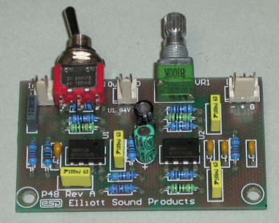
 Please Note: PCBs are available for this project. Click the image for details.
Sub woofers are very popular, with home theatre being one of the driving forces. However, a good sub adds considerably to normal hi-fi program material, and especially so if it is predictable and has good response characteristics. This new version of the P48 subwoofer equaliser is vastly more flexible than its predecessor, so you can get even better control over your sub. The new version of the P48 equaliser allows you to use it with a crossover if desired.
As noted in the original P48 article, the majority of sub woofers use a large speaker driver in a large box, with tuning vents and all the difficulties (and vagaries) that conventional operation entails. By conventional, I mean that the speaker and cabinet are operated as a resonant system, using the Thiele-Small parameters to obtain a box which will (if everything works as it should) provide excellent performance. For the background information, see the original P48 article. This article only describes the new PCB and its functionality.

A quick word is warranted (and repeated) here, to allow you to determine if the speaker you have will actually work in a small sealed enclosure. The EAS principle will allow any driver to extend to 20 Hz or even lower. A good quick test is to stick the speaker in a box, and drive it to 100W or so at 20 Hz - you should see a lot of cone movement, a few things will rattle, but you shouldn't actually hear a tone. A 'bad' speaker will generate 60 Hz (third harmonic) - if you don't hear anything, the speaker will work in an equalised sub.
If a tone is audible, or the speaker shows any signs of distress (such as the cone breaking up with appropriate awful noises), then the driver cannot be used in this manner. Either find a different driver, or use a vented enclosure. The minimum driver size recommended is 300mm (12"), although dual 250mm (10") drivers should work well. Smaller speakers simply do not have enough cone area, and will be limited by their physical size - cone excursion is not a substitute for radiating area.
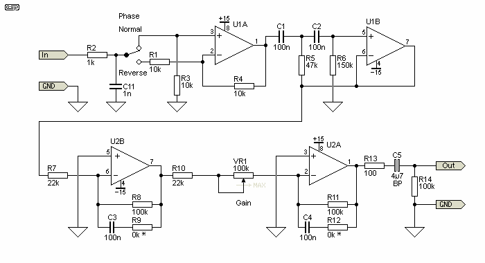
The controller is reasonably simple, and the circuit is shown in Figure 1. An input buffer provides phase switching and ensures that the input impedance of the source does not affect the filter performance, and this is now followed by a 12dB/octave high pass filter. The phase reversal switch is used so that the sub can be properly phased to the rest of the system. If the mid-bass disappears as you advance the level control, then the phase is wrong, so just switch to the opposite position.
The board has only one input, so if you plan to use a normal stereo feed supplying a single P48 board, you'll need to sum the two stereo outputs. This is easily accomplished by using a pair of resistors - the value should be between 2.2k and 4.7k. If this is done, replace R2 with either a 100 ohm resistor or a wire link.

VR1 is used to change the gain of the second integrator. The level through the controller can be set to make sure that there is no distortion - there can be a huge amount of gain at low frequencies, and if the gain is too high, distortion is assured!
The high-pass filter is designed as a peaking type, and gives a response that is almost perfect down to 20Hz. The lowest frequency can be tailored by changing C1, C2, C3 and C4. As shown, the response peaks at 18Hz, but you can use 68nF to increase this to 27Hz, or 47nF for 39Hz. See Table 1 for the full range of values.
The integrators (U2B and U2A) include shelving resistors (R8 and R11), and the capacitor / resistor networks (C3-R9, C4-R12) allow the HF attenuation to be halted at a specific frequency. This will be discussed in greater detail below. The final output level is set with VR1.
It is OK to substitute different opamps, but there is little reason to do so. Do not be tempted to use a DC coupled power amplifier. If the one you are planning to use is DC coupled, the input should be isolated with a capacitor. Choose a value to give a -3dB frequency of about 10Hz, as this will have little effect on the low frequency response, but will help to attenuate the subsonic frequencies.
The unity gain range (using a 100k pot as shown) is from 25Hz to 68Hz. This should be sufficient for most systems, but if desired, the resistors (R7 and R10) can be increased in value to reduce gain, or reduced if more gain is needed. Make sure that the selected gain is not so high as to cause clipping in the P48 circuitry.
| The unity gain frequency is important in only one respect - it will determine the internal gain of the system, and needs to be set based on the input signal level. If the unity gain frequency is set to (say) maximum (68Hz) and you have a 1V RMS input, then a 1V RMS input at 20Hz will severely clip the integrators. The setting for VR1 is determined by the input sensitivity of your power amplifier(s) used on the main system. It is probably easier to experiment a little than try to measure everything. |
To allow lower frequencies, you can increase the 100k shelving resistors (R8 and R11) to 220k, but a much better result will be obtained by increasing the values of C1 to C4. A turnover frequency of less than 10Hz is possible, but expect to use a lot more power, as there will likely be significant sub-sonic energy that will create large cone excursions with no audible benefit.
The input must be a normal full range (or for a biamped system, the complete low frequency signal). Do not use a crossover or other filter before the EAS controller unless you also include suitable values for R8 and R12. These are shown in Table 2. For final adjustment, and to integrate the system into your listening room, I recommend the Project 84 constant-Q equaliser. The end result using this is extraordinarily good - I have flat in-room response to 20Hz!
For the power supply, use the one in Project 05, or anything else will provide +/-15V at a few milliamps. My supply is not even regulated, and the entire system is as close to noiseless as you will hear (or not hear). Construction is not critical - I built my first version on a piece of Veroboard (perforated prototype board), and managed to fit everything (including the power supply rectifier and filter) on a piece about 100 x 40 millimetres with room to spare.
The EAS system is surprisingly easy to set up with no instrumentation. Of course if you have an SPL meter and oscillator you can also verify the settings with measurements. Remember that the room acoustics will play havoc with the results, so unless you want to drag the whole system outdoors, setting by ear might be the easiest. Even if you did get it exactly right in an anechoic environment, this would change completely once it was in your listening room anyway.
It takes a little experimentation to get right, but is surprisingly easy to do. When properly set, a test track (or bass guitar) should be smooth from the highest bass note to the lowest, with no gross peaks or dips. Some are inevitable because of room resonances and the like, but you will find a setting that just sounds 'right' with little difficulty.
I have had many requests for a high power amplifier, and my recommendation is to use the subwoofer amp (Project 68). This is designed specifically for subwoofers. Now, if you wanted a really powerful sub, use two 300mm (12") woofers, with one 250W amp per speaker. A system such as this would be excellent, especially since the effective cone area is greater than the 380mm woofer I am using. A typical 300mm speaker has a cone area of about 0.05 m² versus 0.085 m² for a 380mm unit, so two 300mm speakers will have a total effective cone area of 0.1 m². You could go all the way, with a 300mm driver on each face of a cube, with a 250W amp for each. 1500W of low bass should do the job, especially with a cone area of 0.3 m².
This idea is not as silly as it sounds. With six 200mm (8") drivers, you would get a cone area of nearly 0.13 m² (about the same as a single 450mm (18") driver), and the box would still only be quite small at about 60 litres (my guess). There is a lot of scope for experimentation, with far less chance of a box being completely useless than with conventional ported designs.
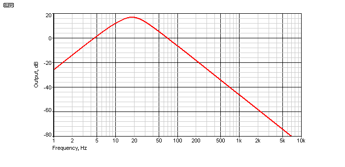
Now we get to the tricky bits. Naturally, you can build the circuit exactly as shown, and you'll get exactly the response indicated below. This has been verified using my speaker measurement software, which allows me to measure response down to 3Hz.
By changing component values, almost any desired response is possible, although this circuit is unable to produce a dip or notch. The enclosure therefore must be the optimum volume for the driver(s) selected. Use of smaller enclosures will result an a peak in the response, and also reduce efficiency even further than may otherwise be the case.

If the circuit is built exactly as shown in Figure 1, you will get the response shown above. The response peaks at 18Hz, and rolls off at 12dB/octave either side of the peak. The unity gain frequency is 68Hz with gain set to maximum. In this configuration, the circuit behaves almost identically to the original P48, but the extreme bottom end is slightly better because of the filter built around U1B.
R9 and R12 are simply replaced with wire links, or suitable low-value resistors (100 ohms for example). To change the peaking frequency, simply alter the values of C1, C2, C3 and C4 as shown in the table below. In all cases, the peak is 16.8dB above the unity gain frequency. Values shown below are with the gain control at maximum (minimum resistance).
| C1, C2, C3, C4 | Peak Freq. | Unity Gain Freq. |
| 120 nF | 15 Hz | 57 Hz |
| 100 nF | 18 Hz | 68 Hz |
| 82 nF | 22 Hz | 83 Hz |
| 68 nF | 27 Hz | 100 Hz |
| 56 nF | 33 Hz | 122 Hz |
| 47 nF | 39 Hz | 145 Hz |
| 39 nF | 47 Hz | 175 Hz |
| 33 nF | 55 Hz | 205Hz |
To be able to use the P48 with a crossover, then you need to add resistance in series with the integrator capacitors. This produces response as shown below. Since the output is no longer attenuated at 12dB/octave for all frequencies, a tailored bass boost circuit allows the crossover frequency to be set, rather than relying on the speaker box alone. This provides a great deal of flexibility that was not available in the original version.

By increasing the values of R9 and R12, the response shown above can be obtained. If your speaker in the box has a -3dB frequency/resonance of (say) 55Hz, you'd use a value of 47k (as shown in the table below). For clarity, only four of the possible frequencies are shown above. As the speaker's -3dB frequency is reduced, so too is the amplitude of the peak. This ensures that the lowest frequencies are boosted by just the right amount to obtain a flat response.
| R9, R12 | +3dB Freq. | Relative Boost at 18Hz |
| 10 k | 246 Hz | 32 dB |
| 12 k | 205 Hz | 29 dB |
| 15 k | 162 Hz | 26 dB |
| 18 k | 134 Hz | 23 dB |
| 22 k | 112 Hz | 20 dB |
| 27 k | 90 Hz | 16 dB |
| 33 k | 74 Hz | 14 dB |
| 39 k | 63 Hz | 11 dB |
| 47 k | 52 Hz | 9 dB |
| 56 k | 44 Hz | 7 dB |
| 68 k | 36 Hz | 5 dB |
You only need to select the value that gives you the closest to your -3dB frequency (this is the same as the resonant frequency of the speaker in the box). Extreme accuracy is not needed, because the response of any subwoofer will vary widely once it's in a typical room. It's worth noting that any loudspeaker + box with a resonant frequency above ~70Hz will almost certainly perform poorly as a subwoofer, so R9 and R12 can be expected to be in the range from 39k to 68k.
As shown, this table assumes that the boost frequency peak is 18Hz, but there is no reason that a different frequency can't be used. One problem is that the interactions are fairly complex, and it is impractical to attempt to show every possibility. If the board is used only for subwoofers (as intended), the normal 18Hz peak frequency is expected to be ideal for most installations.
Please see the original P48 article for background information, references and other information.
 Main Index Main Index
 Projects Index Projects Index
|