
|
|
| Elliott Sound Products | Project 26A |
 Main Index
Projects Index Main Index
Projects Index
|
This is a project that's been waiting for some time, but I finally got my act together, purchased some ICs, and started experimenting. I found quite a few things that no-one else has mentioned (the PT2399 is a very popular delay IC) - some good, some not-so-good. All in all though, this is a capable chip, that does what's needed well and without a great deal of effort. It's also a great deal of fun to play with. 
One application that really needs a delay is the Surround Sound Processor (Project 18) - a standard Hafler matrix that will provide a passable rear channel signal. Even many so-called home-theatre amps use just this to generate the rear channels! In order to confuse the brain, we really need to delay the signal, which makes it sound as if it were further away. This principle is used in virtually all commercial units, but the 'real' ones have a tendency to be somewhat more complex than a simple passive unit (although you may be surprised if you analyse some of these 'specialised' ICs).
The digital delay presented here is expected to be sufficient for most applications, both for home theatre, music production and PA applications (see below for more on this). It provides a variable delay - the minimum is a little over 30ms - fractionally longer than ideal, but I doubt that anyone will hear it as a problem. The shortest reliable delay is 50ms, this is the equivalent of being about 17 metres away from the rear speakers, and they will have a suitably 'distant' sound, even when relatively close to the listening position. The delay can be extended to over 1 second, but high frequency response is woeful - to put it kindly.
The apparent 'distance' created by a delay can be calculated easily - sound travels at about 345mm/ms so 50ms gives 17 metres.
Many commercial units include extra features (different delay periods, reverberation, etc), which can be easily applied to this project if desired. Reverb is generally not useful (it simply clutters the sound, and if reverb is part of the original sound source (from the DVD for example), it will be included anyway. Such effects are great to impress your friends, but will become tiresome after a relatively short time, and end up detracting from the program material - you end up listening to the effects instead of the sound.
To include the repeat function, it's simply a matter of feeding the output signal (via a pot and resistor) to the point marked 'A' on the circuit. A 20k pot and 10k resistor will work well - this is shown in Figure 4. To disable 'reverb', simply set the pot to minimum. Other than for guitar effects, I expect that the vast majority of people will simply leave this out.
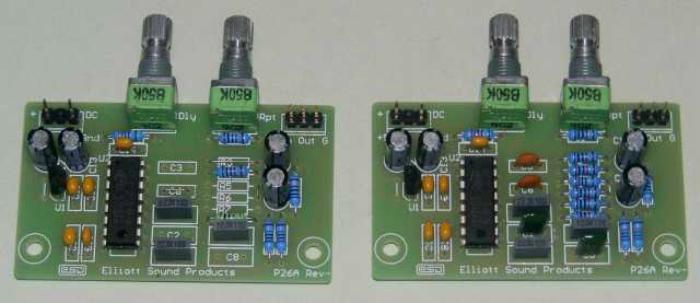
A photo of the two versions is shown above. The one on the left has the minimum filtering, and is suitable for short delays (no more than ~100ms), and that on the right shows the full version. You will note that I used Greencaps for the filter - the PCB layout is designed for MKT style caps as always, but I didn't have any 4.7nF MKT caps in stock. You may also note that the regulator ICs (78L05) appear to be installed backwards. This is a small error on the PCB overlay - and the regulators must be installed as shown in the construction article.
The delay circuit is shown in Figure 1, and uses the Princeton Technology PT2399 digital delay chip. This replaces the original Mitsubishi device described in Project 26. The PT2399 has been around for a while now, and for ages I have planned a project based on it. Until now, I was unable to get any further - however I have now found a source of ICs, so it is worthwhile.
The circuit as described in the data sheet is relatively simple and effective, but I've found that it can be dramatically simplified, with very little loss of performance. The PT2399 data sheet has complete circuit diagrams, but they are rather messy and most of the pin functions are not explained. Likewise, many of the internal functions of the IC aren't explained either - I've been able to decode some, but it's still guesswork on a couple of functions.
The first circuit shown (Figure 1) is (almost) a direct adaptation from the PT2399 data sheet, but with some significant simplifications. As shown it will give good performance over a reasonably wide frequency range. The filters are tuned to around 8.5 kHz (-3dB), and although this could be reduced or increased, there does not seem to be any good reason to do so. This seems to be the optimum response for rear channel speakers, so should be left alone. The filter circuits use internal opamps, and only require the external components shown in Figure 1.
The above schematic is based on the one in the application note, but is changed in quite a few areas. Component values are simplified, and large value electrolytic caps have been replaced by 10µF. Smaller value electrolytic caps have been replaced by 10µF as well. This arrangement has been tested, and there is no apparent noise penalty, despite the reduced filter capacitor values. Having an on-board regulator helps a lot, because it presents the delay IC with a low impedance supply, without the need for large value electrolytic caps.
The 5 Volt supply must be regulated, as anything over 6 Volts will destroy the delay chip. Because of the regulator, it can handle any voltage from 9V up to a maximum of ~15V or so. If a 5V supply is available, the 5V regulator may be omitted and the existing 5V supply used instead. The PT2399 draws a maximum of about 30mA (supply current falls as the clock frequency is reduced and delay is increased). Any existing supply must have enough reserve to supply the extra current. It is essential that the 5V supply has a low impedance, or the internal clock oscillator may not even start, meaning that you get no output at all.
Something that isn't explained at all in the data sheet is the filter topology. The filters are low pass, multiple feedback types, and have a rolloff of 12dB/ octave. The final filter (using R5 and C8) adds an extra pole, making the output filter 18dB/ octave. The actual filters are shown below, so it makes a bit more sense. Showing parts hanging off an IC is not useful to determine exactly what's going on.

The filters shown above are using the PT2399's internal opamps, and are based on (but not identical to) those shown in the data sheet. The simplification I used here is to make all filter resistors 10k, rather than a mix of 10k and 15k. Why? Because the version shown above actually works better, and reduces the chance of errors caused by component mix-ups.
While the data sheet provides a value of 100nF (or inexplicably 82nF for the echo circuit) for C4 and C9, it's hard to justify such a high value. I recommend that you use 33nF caps in these locations, but you can go as low as 10nF.
This is one thing that is rates barely a mention, even though it is covered briefly in one version of the data sheet. C4 and C9 (in Figure 1 & 3) appear to be used for switched capacitor filters, which track (more or less) the clock frequency. The second data sheet I located describes the function of these as 'modulated integrator' and 'demodulated integrator' by adding a capacitor, but has zero details of how this is done in the IC. The block diagram provided in the (slightly) more complete data sheet is not useful (although it does specify that the power supply should be nominally 5V). It also claims that the maximum output is 2V RMS ... in someone's dreams.
With the recommended values of 100nF, the IC starts slew-rate limiting from about 1kHz and above. This means that the signal level at any frequency above 1kHz has to be below the slew rate threshold, so it falls at 6dB/octave from 1kHz. I've tested the delay with these caps reduced to 10nF, and while there is certainly a bit more HF noise, the delay also shows an improved high frequency response and far less slew-rate limiting. 33nF is not a bad compromise, but feel free to experiment.
As it transpires, the circuit can be simplified quite dramatically. So much so, that I've tested the delay with no filters at all, and there is no audible noise. There is quite a bit of visible noise, but it's well outside the audio spectrum and is easily removed with the most rudimentary filter. This is not so effective with very long delays, but the maximum recommended is around 300ms (I've extended it to over 1 second, but high frequency response is severely affected when the delay exceeds a few hundred milliseconds.
Although you may see the input and output multiple feedback filters referred to elsewhere as 'anti-aliasing' filters, they're not. I tested the circuit with the highest audio signals that the delay IC would pass, then beyond ... nothing. There was no aliasing at all. Once the signal passes a frequency determined by the clock (and presumably C4 and C9), the signal first goes into slew-rate limiting, then stops completely at a somewhat higher frequency.
At 2kHz and with the suggested 100nF caps, the maximum signal level is about 500mV RMS, at 4kHz it's 250mV, and so on. If you plan to use the circuit for short delays only, the value of C4 and C9 can be reduced - tests with 10nF gave good results and low noise (without any additional filtering) with delay times up to about 50ms. For longer delays - as used for an echo pedal for example - I recommend that C4 and C9 should not be reduced below 33nF.
Also not mentioned anywhere ... if total value of R10 and the optional pot is less than around 2k, the oscillator probably won't start, and you'll get no signal. If you need less than 50ms delay, it will probably prove necessary to include a timer circuit (see Fig. 4) so the oscillator will start reliably. The transistor connects the timing resistor and/or pot to ground after a short delay. Once the oscillator is running, it seems to be quite stable. The transistor solution works fine - this is shown in Figure 4. Note that this may or may not be a problem, depending on the batch of ICs you get.

The version shown above is suitable for use as a fixed short delay, and makes a surprisingly good account of itself. As you can see, the circuit is dramatically simplified, with most of the filter components simply deleted. Because it's expected to be operating at a clock frequency of around 15MHz, the simplifications do not cause any loss of audio quality - if anything, it's better than with the fully configured filters. Response extends down to about 10Hz - it can go even lower, but there's no point. Overall, this is the version I recommend. It uses fewer parts, and works just as well (if not better than) the 'full blown' version in Fig. 1.
High frequency response is considerably better than the Fig. 1 circuit, and easily extends to 12kHz. Believe it or not, it's even possible to leave out C3 (1nF) and C8 (10nF). I have tested the circuit extensively with no filters at all (apart from what I assume to be the switched capacitor filters using C4 and C9), and with short delays there is almost no visible noise, and no audible noise. With long delays, if there is considerable HF content in the audio signal, you may hear distorted sibilants and some other artifacts. In general though, I'd be perfectly happy to use it just as shown. For guitar (or other musical instrument applications), it would be better to increase the value of R8 back to 2.7k. This will roll off the higher frequencies, and the echo/reverb effect is more natural. Real echoes usually have a rapidly diminishing HF content as these signals are absorbed/ diffracted easily, including absorption by the air itself.
I included the 'repeat' pot and connections in this, and it's done in exactly the same for the version shown in Figure 1, except it's not shown. This is the basis for a reverb or echo effect, but as noted below, a single delay does not make a nice sounding reverb or echo. Also not shown is a method of modulating the clock frequency and hence delay time. This can become the basis for a tremolo circuit, but if used for that there will be a delay between striking a note and hearing it - this is surprisingly easy to hear (and makes it hard to play, even with only 50ms delay). Try standing 17 metres from the speakers and trying to play normally - it's not easy!
I'd love to be able to claim that it can be used for flanging effects as well, but the minimum delay is simply too great, and it won't work in this role. This is the one major complaint I have with the PT2399 - the minimum delay is too long, precluding it from many applications.

If you really want to use the minimum possible delay time (and your IC refuses to start with a low value timing resistor), you can add this simple transistor delay to the timing circuit. The 47µF cap is charged via R1 (10k resistor), and the base is supplied from the R2 (also 10k). Interestingly, the oscillator won't run if the timing resistor is open circuit, but it will start once a connection is made. This is in contrast to operation with a value below 2k - it not only won't start, but it cannot start even if the resistance is increased. A lockout condition such as this is unacceptable, so the above circuit was devised to get around it. The delay is about 50ms - long enough for the PT2399 to get its act together. This has been tested fairly extensively, and I'm satisfied that it will solve startup problems even with very low values for R10. The delay can be increased if necessary by increasing the value of C1.
The circuit as shown needs to be driven from a low impedance - no more than perhaps 1k. Output impedance is fairly low, but the 2.7k (or 1k) final filter resistor means that the load should be at least 10k. There is one thing that has considerable nuisance value, and that's the limited voltage that the IC can handle. In many cases, it will be necessary to attenuate the signal before it gets to the delay circuit, and boost it again afterwards.
There is no specified maximum level in the data sheet, but testing reveals that it needs to be kept to no more than around 1 Volt RMS. The level must be below the maximum or distortion will be plainly evident. The output from a CD/DVD player is generally about 2V, so you may need to attenuate the input signal by 6dB, and provide 6dB of gain afterwards to get the level back again. It can be reduced (and amplified) more, but at the expense of noise.
The necessary gain (and optional mixing) stages can use basic opamp circuits, or Project 94 ('universal' preamp/ mixer) can be employed for everything.
The following table is taken from the data sheet, and shows the delay time for various values of the timing resistor. I remain unconvinced that the figures shown are necessarily very accurate, and it's certain that there will be variations from one IC to the next. Delay times in excess of 200ms cause audible distortion, shown shaded in the table. You can certainly use the delay with even greater delays than shown, but you will hear the distortion through any halfway decent speakers.
| R t | 27.6 k | 21.3 k | 17.2 k | 14.3 k | 12.1 k | 10.5 k | 9.2 k | 8.2 k | 7.2 k | 6.4 k |
|---|---|---|---|---|---|---|---|---|---|---|
| f clock | 2.0 M | 2.5 M | 3.0 M | 3.5 M | 4.0 M | 4.5 M | 5.0 M | 5.5 M | 6.0 M | 6.5 M |
| Delay | 342 ms | 273 ms | 228 ms | 196 ms | 171 ms | 151 ms | 137 ms | 124 ms | 114 ms | 104 ms |
| THD | 1% | 0.8% | 0.63% | 0.53% | 0.46% | 0.41% | 0.36% | 0.33% | 0.29% | 0.27% |
| R t | 5.8 k | 5.4 k | 4.9 k | 4.5 k | 4.0 k | 3.4 k | 2.8 k | 2.4 k | 2.0 k | 1.67 k |
| f clock | 7.0 M | 7.5 M | 8.0 M | 8.5 M | 9.0 M | 10 M | 11 M | 12 M | 13 M | 14 M |
| Delay | 97 ms | 92 ms | 86 ms | 81 ms | 76 ms | 68 ms | 62 ms | 57 ms | 52 ms | 48 ms |
| THD | 0.25% | 0.25% | 0.23% | 0.22% | 0.21% | 0.19% | 0.18% | 0.16% | 0.15% | 0.15% |
| R t | 1.47 k | 1.28 k | 1.08 k | 894 | 723 | 519 | 288 | 0.5 | ||
| f clock | 15 M | 16 M | 17 M | 18 M | 19 M | 20 M | 21 M | 22 M | ||
| Delay | 46 ms | 43 ms | 41 ms | 38 ms | 37 ms | 34 ms | 33 ms | 31 ms | ||
| THD | 0.15% | 0.14% | 0.14% | 0.14% | 0.13% | 0.13% | 0.13% | 0.13% | ||
As noted earlier, if the value of Rt (the timing resistor) is less than 2k, the oscillator may not start when power is applied. There does not appear to be a way to fix this within the chips internal architecture. If it happens, you must ensure that the value is always high enough to ensure a reliable start. This means that the delay is going to be around 50ms - some may consider that to be too long. A basic timing circuit as shown in Figure 4 is one fix, or you can just live with a 50ms delay (which is actually not too bad based on listening tests). Of course, you can include a pot to change the delay, but you have to remember to set it for a reasonably long delay before powering on the unit. The transistor solution is the best, and is configured to be open-circuit initially, and turns on (shorting the 'earth' end of the pot to ground) after a delay.
For what it's worth, I also measured the clock frequency on pin 5. I obtained 24.25MHz with Rt = 100 Ohms, 13.05MHz with Rt = 1.4k and 1.58MHz with Rt = 27k (the frequency with 100 Ohms is higher than claimed, and that with 27k is quite a bit lower than claimed). Don't be misled into thinking that the delay clock is also used for the A/D and D/A conversion - it isn't. I measured the clock residual at the output to be 34.7kHz with Rt = 25k, and 540kHz with Rt = 100 ohms. The A/D and D/A (CODEC - coder/decoder) clock frequency also varies with signal amplitude (much like with self oscillating Class-D amplifiers), as does the residual signal level. The CODEC clock frequency is at its highest at low amplitudes, and falls as the signal voltage approaches the positive or negative peaks.
A complete surround system would consist of a power supply, the decoder matrix, optionally a stereo width controller, perhaps a Project 09 electronic crossover, and the delay unit. I have not provided a diagram here, as there are so many possibilities that a single diagram can't hope to cover the available options. There is a 'full surround' system block diagram in the original Project 26 article, and most of that is relevant - at least up to a point.
A somewhat more complete version of a surround-sound decoder is described in Project 188, which is a better proposition than the original described in Project 18. This 'Mk II' version was published in May 2019, and should suit most constructors. All PCBs for it are available, and require minimal modifications to achieve a rather good outcome, for not too much expenditure.
This module is ideal for a digital echo machine, and can also handle reverb. However, most musicians will have heard a typical (basic) digital echo/reverb, and they sound awful. Because there is only one time delay, the reverb sounds very unnatural, as does echo. To duplicate an old analogue multi-head tape echo (the holy grail for some), you need two or three delays, with each set according to the sound you want. Each can have individual or shared feedback, and it becomes possible to get a wide variety of sounds, with a much more natural effect than with a single delay. Not only that, but you also get some great effects. And yes, the PT2399 can have a voltage controlled time delay as well - more fun.
While a complete description of how this can be done is outside the scope of this project article, if enough people are interested I'll develop the system and publish it as a separate project. Suffice to say that 3 delay units and a P94 universal preamp/ mixer is all you need, but there are many varying levels of sophistication and complexity that can be applied. Even in its simplest form, the results can be expected to be at least as good as one of the better analogue tape units - with the added benefit of not having to replace tapes!
While this delay is not suitable for high quality audio, it's ideal for a speech PA system using re-entrant horn speakers. In many cases, the area to be covered is such that listeners will be able to hear the sound from two or more speakers located at different distances. This causes an echo effect that is not just disconcerting, but can make the announcement completely unintelligible. If the system is intended for emergency evacuation (a shark sighting at the beach for example) having unintelligible speech is dangerous.
If used in this way, one has to be careful that the speakers are oriented in one direction - a traditional omni-directional speaker array at each speaker location won't work. See the diagram below to see how speakers should be used in this arrangement. Needless to say, it is expected that the speakers will all be driven from 'constant voltage' 100V (or 70V for the US) line amplifiers. The exact delay has to be calculated based on the distance between speakers, and although it will change depending on air temperature and humidity, there is usually no requirement to re-adjust the delay provided the distance between speakers is not too great. Human hearing is normally tolerant of echo signals that arrive within ±10ms (3.45 metres), but as little as 30ms is audible though probably acceptable in this application. Do not believe it when you see references that claim we don't hear anything less than 1/15th second (60ms) - Wikipedia is very, very wrong on that score! (It's so bad that I won't provide a link, as that only gives it undeserved credibility.)

Figure 6 - Delayed PA Application
The arrangement shown above is only an example, and speaker height and spacing has to be determined by acoustic modelling or empirically, based on the terrain, nearby buildings, etc. As shown, the system is capable of providing excellent coverage, and with correct speaker placement, aiming and delay, there will be a consistent level across a wide area. Because there is a greatly reduced opportunity for an echo effect from the speakers, intelligibility is greatly improved. Note that speakers also have to be aimed to prevent echoes from nearby buildings, or much of the benefit is lost.
So, how exactly does the delay help here? If you are in position 'A', it does you no good at all - which is as it should be. Ideally, you will only hear sound from speaker tower 1 ... assuming that there are no buildings to reflect sound back at you of course. However, if you are at position 'B', you will hear sound from tower 3, and a quieter version of the same thing from tower 1. Without any delay, you will hear the sound from tower 1 as an echo, because it is delayed due to the distance between you and the tower. With delay added to the signal to tower 3, the signal from both towers reaches you at the same time. Wind, temperature and humidity will change the timing a little, but usually not enough to cause complete loss of intelligibility. By eliminating the echo effect a significant improvement can be achieved.
Should you be in position 'C', you will hear tower 4, a smaller amount from tower 2, and a smaller amount still from tower 1. All sounds will be delayed, either by the air or by the electronic delay lines, so again, you hear the sound clearly with no (or very little) echo. The requirement for directional speakers is obvious - a listener at position 'A' would hear a very pronounced echo if the speakers on tower 2 were omni-directional.
A person standing below towers 2, 3, 4 & 5 will usually hear roughly the same level from the speakers overhead and from the next tower towards the centre. You can imagine how bad the sound will be if no electrical delay is incorporated. Equal levels from two locations, with the more distant one delayed by ~100ms! Add in the often terrible enunciation of most 'live' announcers and the chances of you actually understanding a warning or other message are not good at all.
There is nothing new in the above - delayed feeds are common in large arenas and anywhere else that requires good intelligibility and a freedom from acoustic 'clutter' caused by echoes from other more distant speakers in the listening space. Providing the delay is usually a rather expensive exercise, but it needn't be, especially when the programme material is speech band (nominally 300Hz to 3,500Hz) and true high fidelity isn't expected or needed.
This technique is not a panacea - there are limited places where it will work as well as one would hope, but if set up properly it's often an excellent way to ensure that you can actually make announcements that people can not only hear, but understand, rather than just creating a cluttered and unintelligible noise that many people will not comprehend at all. Be aware that it will not work within a highly reverberant space - echoes from walls or roof areas will destroy intelligibility no matter what you do. Acoustic treatment is the only solution. Although electronic cancellation could be adapted, that will only work at comparatively low frequencies (think 'noise cancelling headphones for example).
The power supply described in Project 05 or Project 05-Mini are ideal for this project. Either will power everything easily. The P94 (or other) preamp/ mixer board needs ±15V, and the +15V supply can also run the delay unit(s). There are too many possibilities to list, and too many ways that the delay circuit(s) can be interconnected to attempt to cover them all.
| Main Index
Projects Index
|