
|
|
| Elliott Sound Products | Magnet Charger |
 Main Index
Clocks Index
Main Index
Clocks Index
Ok, so magnets don't actually 'wear out', but they do lose strength over time. This is especially true of earlier magnets, since most modern magnetic materials were unknown before the second world war. For example, Bulle clocks use either a carbon steel or cobalt steel magnet (there is conflicting information on this), and the relatively poor performance of the material and the rather odd way the magnet is created (with a 'N' pole in the middle, and 'S' poles at each end) ensure that the magnet will lose strength over time. It is fairly safe to say that most Bulle clocks will need their magnet rejuvenated before they will run properly from the normal single 1.5V cell.

| The first 'real' magnet material was cobalt-chrome steel, in 1921 [ 1 ]. Prior to that, carbon steel was hardened by heating and quenching, and was the basis of most magnets used. Modern magnetic material commenced in around 1932 with the invention of Al-Ni-Fe (aluminium, nickel, iron) which later became Alnico (aluminium, nickel, cobalt). Alnico was considered a quantum leap above earlier materials. It wasn't until some time later that today's really powerful magnetic materials became generally available. So-called 'rare-earth' magnets were not produced commercially until the 1960s, with Samarium-Cobalt being the first offering. The most powerful magnets currently available are neodymium (neodymium-iron-boron, NdFeB) - these were invented in 1983, but were not readily available until some time later - well after Bulle clocks ceased production. [ 2 ] |

Figure 1 - Side View of Completed Magnet Charger
The way any magnet is 'charged' is to subject it to an intense magnetic field - the more powerful the field, the better. It is not uncommon to simply wind a coil around the magnet and briefly connect it to a car battery, but this method is fraught with danger. Should the 'contact' end of the wire become welded to the battery terminal, the coil and its supply wires will probably melt. The molten metal droplets can cause much damage to feet, arms, hands and the car's paint work, and if an arc is drawn it has a very high ultraviolet content and can damage your eyes.
As a result (and also because I had almost everything I needed in my junk box), I decided to put a charger together. Bear in mind that this will be an extremely expensive project if you have to purchase everything new. Even if you can get the bits from eBay, it will still be expensive.

Figure 2 - Circuit Diagram of Magnet Charger
The circuit diagram is shown above. A TRIAC is used to switch the AC, because the peak charging current is far too high for any small push-button switch. The ballast resistor (shown as 'HOT' in the photo) reduces the current to a manageable level, but it's still around 15A when the 'Charge' button is first pressed. The only things limiting the current are the transformer's winding resistance and the ballast resistor. The TRIAC I used is now obsolete, but is rated for 400V and 25A continuous current. Peak current is 250A, and the transformer can't supply anywhere near that. For the TRIAC, you can use TIC246D, BTA25-400, BTA41-600 or similar. It's used in the low-voltage section so that it doesn't have to be insulated to prevent contact, so it's low voltage, high current.
Because the TRIAC and SCRs that I used are 'new-old-stock', it's unlikely that you'll be able to get them anywhere. The 2SF753A SCRs I used are rated for 300V, 11A continuous or 125A peak, and can be replaced by anything similar (or better). You can use the CS35-08, rated for 600V and 120A and two of those would be sufficient (the series resistors will need to be half the resistance and at least double the current handling ability). Another candidate is the CS45-16 (1,600V, 43A), which appears to be cost effective. Personally, I'd still prefer to use four SCRs to share the current, even if it looks like fewer would handle the current. If possible, get SCRs in a TO247 style (flat package) as they are far cheaper than the stud-mounted types I used.
A normal (cheap) 25A bridge rectifier converts the AC into DC, and this is stored in the two 100,000µF (100mF) capacitors. These are very substantial devices indeed, with heavy duty screw terminals. The two are joined using two aluminium busbars, 3mm thick and about 20mm wide. Four 11A (125A peak) SCRs are used to dump the full charge in the capacitors into the coil that is wrapped around the magnet to be revitalised.
The charge held in the caps is typically rated in Joules. In this case, the DC voltage gets up to 75V, and the energy stored is calculated by ...
Charge = ( ½ C ) × V² Where C is capacitance in Farads and V is voltage. This equals ...
Charge = ( ½ 0.2 ) × 75² = 562 Joules
The four 0.5 Ohm resistors serve two purposes. Firstly, they force the SCRs to conduct more or less equally, since the internal resistance of an SCR is extremely low - well below 0.5 Ohm. Secondly, the resistors limit the peak current. With the values shown, the theoretical peak current through each SCR is 150A (75V and 0.5 Ohm), but it is actually somewhat less. A measurement taken on the unit shows the peak current through each SCR and resistor to be around 120A - the total peak current is 4 times this, or 480A. The total current remains above 320A for about 12 milliseconds, after which it falls away to zero after about 100ms. Instantaneous dissipation in each 0.5 Ohm resistor is over 7kW! Although the time is brief, these resistors get extremely hot when the unit is fired.
The TRIAC used to switch the AC means that a low power momentary pushbutton switch can be used to charge the caps. The 2 Ohm ballast resistor also gets very hot when the button is pressed - this resistor looks like a wire, stretched along the edge of the unit (see Figure 1). When the 'charge' button is pressed, the ballast wire glows red !
The bridge rectifier and TRIAC are mounted on the aluminium channel that forms part of the capacitor restraint. This provides excellent heatsinking, but it isn't really necessary to go to that extent. Even after repeated charge/discharge cycles, the channel section doesn't even get warm.
The four SCRs can be seen on the right, just above the ends of the two caps. They are directly mounted (no electrical insulation) on a 3mm aluminium busbar. Again, this doesn't even get warm in use. You can also see the meter, although a better view is shown below. The meter is simply to let you see the charge voltage, and it is possible to press the charge button for the right amount of time needed to achieve any voltage you like. 99% of the time, the full charge will be used.
The images below give a really good view of the 0.5 Ohm resistors. These are simply lengths of Nichrome wire that has been wound into a small coil. Commercial resistors cannot be used! The current is so high that they will become open-circuit the very first time the 'Fire' button is pressed. The Nichrome wire is 0.7mm diameter (same for the ballast resistor) and is sufficiently rigid that the resistors should outlast the capacitors.
Even though the caps are heavy duty, they were never designed to withstand the discharge current expected of them in this application. I don't know how long they will survive, but on the positive side, the unit will not be used very often. Discharge currents of the magnitude described here are very hard on all the components. Even the small coil shown attached to the terminals will distort itself if the caps are discharged without a magnet (or soon to be magnet) inside the coil. The field strength is insufficient to crush aluminium cans (look up 'can crusher' on your favourite web search-engine), but is more than acceptable for the intended purpose.

Figure 2A - Circuit Diagram of Alternative Magnet Charger
The alternative (which will be about the same cost overall) is shown above. The MOSFETs shown (IRFP4310ZPbF) are rated for 120A continuous, with a pulse capability a rather substantial 560A. By using three in parallel, this means that the total current rating is 1.68kA. You do need a small 12V supply to provide gate current, and the gate leads must be kept as short as possible. The 15V zener diode is used to clamp the maximum gate voltage to +15V, which may otherwise be exceeded during switching. It must be returned directly to the common source (output) bus, and note that the negative supply from the 12V PSU connects to the positive output, not to ground. At the time of writing, this combination has not been tested, so if you decide to use the Figure 2A circuit before I've tested it thoroughly, you do so at your own risk!
Because there is almost nothing to limit the discharge current (other than the wiring and internal impedance of the capacitors), you can expect the storage caps to have a harder job and possibly reduced life. The current capability is extremely high, so great care is essential. As noted, you build this version at your own risk entirely. Different MOSFETs can be used, provided they have an adequate voltage and current rating. 100V is the minimum, and aim for MOSFETs that can handle at least 100A continuous, and have a suitable pulse current rating. All wiring must be of a gauge suitable for an instantaneous current of at least 500 amps.
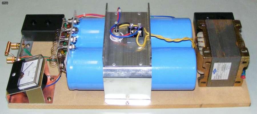
Figure 3 - (Other) Side View of Magnet Charger
Above, you can see the rest of the charger. The meter indicates the charge voltage, and you can see the SCR mounting quite clearly. The 'button box' has since been marked to show which button does what - the button closest to the front edge is the 'Fire' button. Mains is switched on and off at the switched, fused, IEC socket installed in the other black box.

Figure 4 - Full Frontal View of Magnet Charger
Here you can see the 4 x 0.5 Ohm resistors very clearly - they are the little silver coloured coils on the piece of fibreglass PCB material. Each is attached using an M4 screw, because Nichrome cannot be soldered. The copper on the rear of the fibreglass was 'mechanically etched' using a rotary engraver. The four SCR gates connect to a 100 Ohm resistor as shown in the schematic.
You can just see the four SCR gate resistors, directly above the top edge of the fibreglass. These limit the gate current to a safe value, and also ensure that all SCRs get gate current when the switch is closed. Without these resistors, one or perhaps two SCRs would 'steal' all the gate current and the others wouldn't fire at all.
While the magnet charger described will be perfectly alright for the use I will put it to, naturally it is also possible to use an automated charge system. This can easily be devised to provide a known fixed voltage with a simple on/off regulating system using the TRIAC to switch the AC on and off as needed to maintain a fixed voltage. The circuit would have to be arranged to ensure that the AC is disconnected before the SCRs are triggered, and AC must remain off until the SCRs have completely discharged the capacitors.
While it would be fun to add these niceties, there is simply no requirement for an automated system for occasional use. If I were repairing lots of Bulle clocks it would be very useful, but this is unlikely to happen.

Figure 5 - Right Hand Rule for an Energised Coil
It is useful to remember the "Right Hand Rule" as applied to energised coils. Particularly with Bulle clocks, the magnet's polarity is important, otherwise the clock requires the opposite battery polarity from that normally used. By using the Right Hand Rule, it is possible to ensure that the Bulle magnet is charged with a dual North pole in the centre, and South poles on either end. This is shown in Figure 6. Note that there are actually two north poles - it only seems like there is one. All magnets have two poles, so the Bulle magnet is really two magnets on the same piece of steel. This is the main reason that the magnet weakens over time - the material is poor by modern standards, and the North poles are in perpetual opposition. I'm sure it seemed like a good idea at the time. 

Figure 6 - Bulle Clock Magnet Winding Detail
The turns direction and polarity are important. If either is reversed, the magnet will have a south pole in the centre, and the battery polarity must be reversed before the clock will run. To maintain originality, it's obviously better to make as few changes as possible. The red arrows (near the positive terminal) indicate 'conventional' current flow (from positive to negative), upon which the Right Hand Rule is based.
As noted in the drawing, the coils must be close wound -they are shown expanded for clarity. The coils should also be fairly tight around the magnet, and wound with the heaviest gauge wire you have available. Make sure that there are no sharp projections on the magnet or kinks in the wire that may damage the thin enamel insulation. The Bulle 'horseshoe' magnet is shown, but the same principle applies to any Bulle magnet, regardless of shape.
A photo gallery if the unit built by a reader can be seen in the ESP Gallery (Klaus S). The images were shown here, but have been moved to minimise duplication.
I must admit that my efforts have been showed up rather spectacularly by Klaus Sehi (from Landsberg am Lech / Germany) who built a unit and sent photos which are shown in the gallery. I can only say that he did a beautiful job, and he's used the 'charger' to revitalise a Bulle magnet (raising the Field strength from 8mT (milli-Tesla) to just under 33mT). The photos are shown in the gallery, and are published with his permission.
The workmanship is excellent, and it looks like a 'real' piece of equipment. By comparison, mine is 'utilitarian' - it does the job, but lacks any finesse. The heatsink visible above the meter is for the bridge rectifier. All wiring is of a suitably heavy gauge to ensure maximum current, and the high power resistors are well supported.
I congratulate Klaus for a superb build of the 'charger', and the photos are included here as inspiration for others. I have no idea how many of these units have been made, but this one is a stand-out example in all respects.
1 Arnold Magnetic Technologies
2 Magnetic Alloys - Cobalt Development Institute
Main Index
Clocks Index